Quantifying liquid-discharging structure with middle exhaust pipe

A technology of exhaust pipe and liquid discharge pipe, which is applied in fixed measuring chamber, chemical instrument and method, feeding device, etc., can solve the problems of inability to stably discharge liquid, inability to discharge gas from lower container, difficult to realize, etc.

Inactive Publication Date: 2011-10-12
WUXI GREENSTEK
View PDF3 Cites 4 Cited by
  • Summary
  • Abstract
  • Description
  • Claims
  • Application Information

AI Technical Summary

Problems solved by technology

[0002] In some chemical reactions, it is necessary to provide the reactor with a given volume of reaction liquid in stages, but this is difficult to achieve in actual operation; in addition, in the process of liquid discharge of reaction liquid, the conventional double-pipe liquid method cannot The gas in the lower container is discharged, which will cause a pressure difference between the upper and lower containers, that is, the liquid cannot be stabilized

Method used


Image

  • Quantifying liquid-discharging structure with middle exhaust pipe
  • Quantifying liquid-discharging structure with middle exhaust pipe

Examples


Embodiment Construction

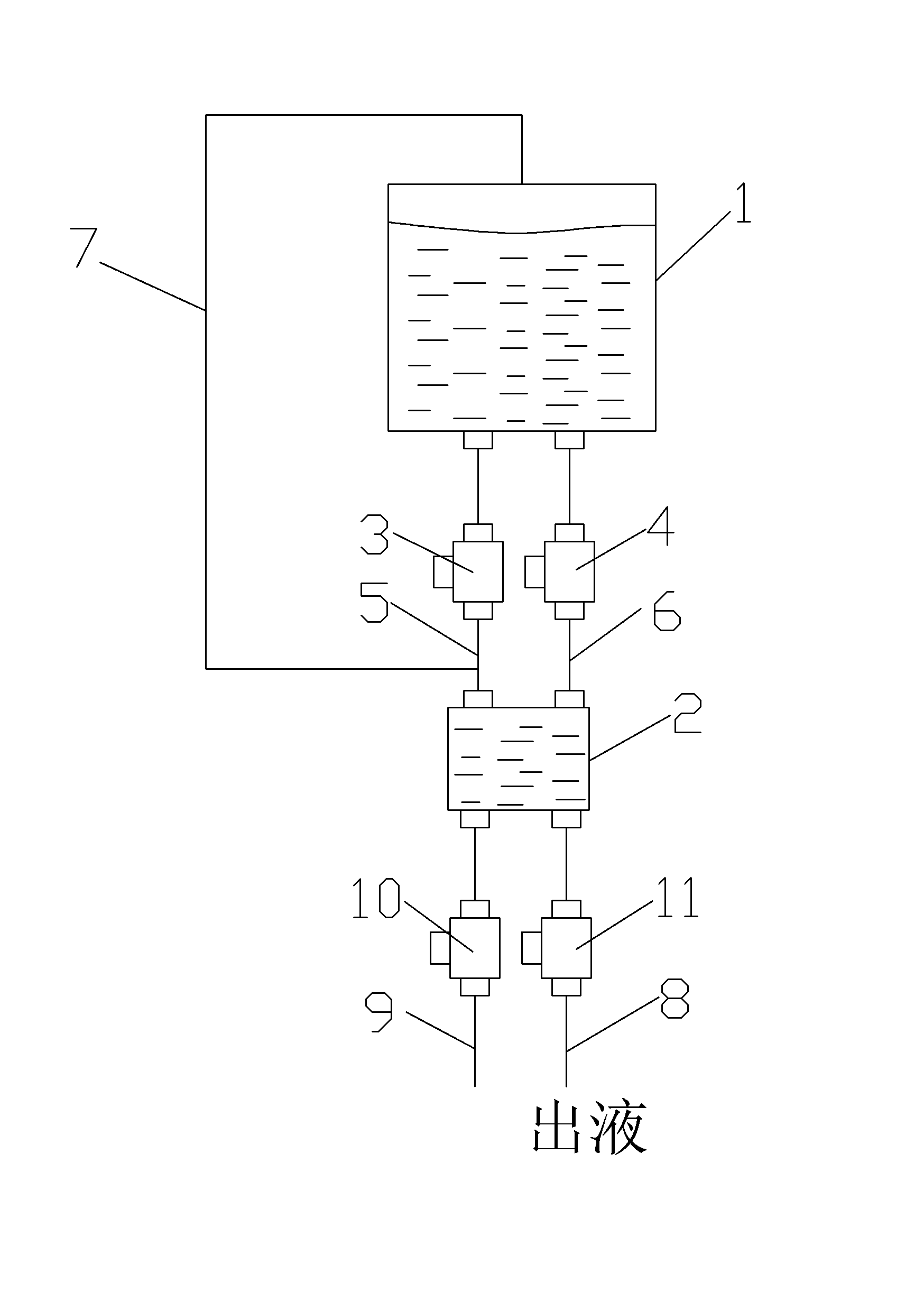
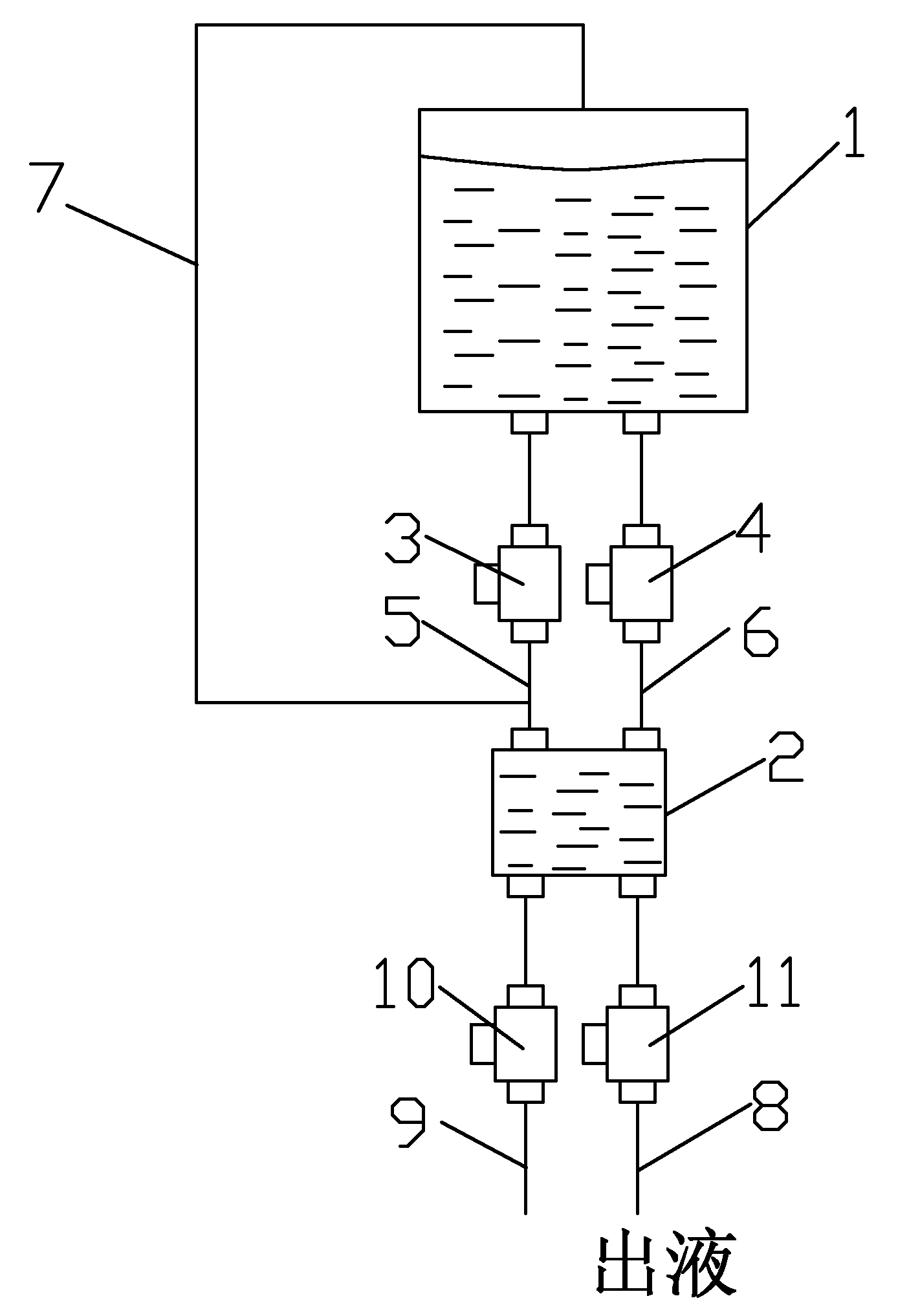
[0008] See figure 1 , which includes a solution tank 1, a quantitative tank 2, a liquid discharge pipe 8 and an air inlet pipe 9 below the quantitative tank 2, the bottom of the solution tank 1 is connected to the top of the quantitative tank 2 below it through two intermediate liquid pipes 5 and 6, and the two The middle liquid pipes 5 and 6 of the roots are equipped with middle solenoid valves 3 and 4, and the bottom of the quantitative irrigation 2 is respectively equipped with a liquid discharge pipe 8 and an air intake pipe 9, and the liquid discharge pipe 8 and the air intake pipe 9 are all equipped with a bottom electromagnetic valve 10. , 11, one end of the middle exhaust pipe 7 is connected to the middle liquid pipeline 5, and the other end is connected to the top of the solution tank 1, and one end of the middle exhaust pipe 7 is located between the middle solenoid valve 3 and the quantitative tank 2, and the middle solenoid valves 3, 4 All open and close simultaneou...


PUM


Abstract

The invention provides a quantifying liquid-discharging structure with a middle exhaust pipe, which ensures the constant volume of discharging liquid each time, i.e. is capable of stably discharging liquid in a quantifying way. The quantifying liquid-discharging structure comprises a solution tank, a quantifying tank as well as a fluid-discharge pipe and an air inlet pipe below the quantifying tank. The quantifying liquid-discharging structure is characterized in that the bottom of the solution tank is communicated with the top of the quantifying tank below the solution tank through the two middle liquid pipelines, middle electromagnetic valves are respectively installed in the two middle liquid pipelines, the fluid-discharge pipe and the air inlet pipe are respectively installed at the bottom of the quantifying tank, lower electromagnetic valves are respectively installed in the fluid-discharge pipe and the air inlet pipe, one end of the middle exhaust pipe is communicated with one of the two middle liquid pipelines, the other end of the middle exhaust pipe is communicated with the upper part of the solution tank, the middle electromagnetic valves are opened and closed at the same time, the lower electromagnetic valves are opened and closed at the same time, and the middle electromagnetic valves and the lower electromagnetic valves are opened and closed at different times.

Description

technical field [0001] The present invention relates to the technical field of the structure of quantitative feeding, in particular to the quantitative feeding structure with an intermediate exhaust pipe. Background technique [0002] In some chemical reactions, it is necessary to provide the reactor with a given volume of reaction liquid in stages, but this is difficult to achieve in actual operation; in addition, in the process of liquid discharge of reaction liquid, the conventional double-pipe liquid method cannot The gas in the lower container is discharged, which will cause a pressure difference between the upper and lower containers, that is, the liquid cannot be stabilized. Contents of the invention [0003] In view of the above problems, the present invention provides a quantitative feeding structure with an intermediate exhaust pipe, which ensures that the volume of each feeding is constant, that is, it can stably quantitatively feeding. [0004] The technical s...

Claims


Application Information

Patent Timeline
Patent Type & Authority Applications(China)
IPC IPC(8): B01J4/02G01F11/28
Inventor 胡鸣若周伟林恽瑞刚小笠原亮曹广益
Owner WUXI GREENSTEK
Why Eureka
Try Eureka