Electrostatic spraying array system and optimizing method thereof

A technology of electrostatic spraying and optimization method, which is applied in the direction of spraying device, spray discharge device, etc., which can solve the problems of complex inefficiency, low deposition speed, and the spraying area cannot be completely covered and overlapped.

Inactive Publication Date: 2011-10-12
顾文华
View PDF6 Cites 8 Cited by
  • Summary
  • Abstract
  • Description
  • Claims
  • Application Information

AI Technical Summary

Problems solved by technology

However, there are two main problems in the design of traditional electrostatic spraying arrays: one is that adjacent nozzles cannot be too close to each other, so as to avoid interference caused by the mutual influence of their electrostatic fields, but this often leads to poor film uniformity or low deposition speed, etc. Problem; Second, the injection area between adjacent nozzles cannot be completely covered or overlaps too much, which is likely to cause periodic defects
However, this solution is limited by the speed of mechanical movement (too fast will affect the spray effect, too slow will affect the uniformity), and it is easy to form new periodic fluctuations or defects, and difficult to optimize for different applications, is a complex and inefficient solution
This design problem has greatly hindered the practical application of electrostatic spraying arrays, so that the current electrostatic spraying technology is still dominated by a single nozzle, mainly relying on methods such as moving the substrate to achieve large-area spraying, and has not been used in applications such as large-area thin film deposition. Can give full play to the inherent advantages of electrostatic spraying, such as easy replication and linear expansion

Method used


Image

  • Electrostatic spraying array system and optimizing method thereof
  • Electrostatic spraying array system and optimizing method thereof
  • Electrostatic spraying array system and optimizing method thereof

Examples


Embodiment Construction

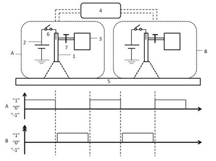
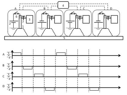
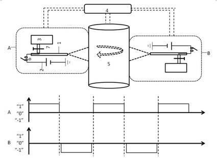
[0020] As shown in the figure, an electrostatic spraying array containing two or more electrostatic spraying units, each electrostatic spraying unit may include some or all of the following devices: an electrostatic spraying nozzle 1, a charge generation and injection device 2 , a liquid storage and transport device 3, an automatic control device 4 for realizing a specific switching pattern, a jetting substrate 5, a switch 6 for controlling the charge generation or injection path, and a switch for controlling the liquid storage or transport path 7. Different electrostatic spraying units can be independent from each other or can share some devices or be part of each other; the devices can be physically separated or have no clear boundaries; some devices can be omitted according to the situation; and so on.

[0021] The typical form of nozzle 1 is tubular, or capillary, cavity, surface with raised points or other shapes that can realize electrostatic spraying; the liquid sprayed...


PUM


Abstract

The invention provides an optimizing control method of an electrostatic spraying array system, which belong to the technical field of electrostatic spraying. The electrostatic spraying array system comprises at least two electrostatic spraying units and is characterized in that each electrostatic spraying unit comprises a charge generating or injecting switch (6) which is independent or shared by other electrostatic spraying units and a liquid flow rate control device or a liquid conveying switch (7) which is independent or shared by the other electrostatic spraying units; the electrostatic spraying array system also comprises an automatic control device (4) which is connected with the charge generating or injecting switch (6) and the liquid flow rate control device or the liquid conveying switch (7); and the automatic control device (4) controls the switching modes of spray heads, namely the spray switching state, time and period of each spray head through one of the following modes or combination of the several modes: controlling charge generating or injecting channels, or liquid flow rates or liquid conveying on-off states. The invention has the characteristics of high practicability, uniform spray and capability of being massively used inindustrial production.

Description

technical field [0001] The invention relates to an electrostatic spraying array system and its optimization method. By controlling the switching state and time of each spraying unit in the electrostatic spraying array, a specific switching mode is realized to achieve a specific spraying effect, such as uniform spraying or periodic patterns, etc. , belongs to the field of electrostatic spraying technology. Background technique [0002] Electrostatic spraying is a technology that uses electrostatic force to disperse liquid to produce fine droplets with static electricity. Its basic physical principle has been explained by the leakage medium model proposed by G. Taylor and J. R. Melcher in the 1960s. See Annual Review of Fluid Mechanics, 1969, 1, 111-146, Electrohydrodynamics: A Review of the Role of Interfacial Shear Stresses and other documents. Electrostatic spraying technology has been widely used in the fields of large biomolecular mass spectrometers, industrial spraying,...

Claims


Application Information

Patent Timeline
Patent Type & Authority Applications(China)
IPC IPC(8): B05B5/025B05B12/00
Inventor 顾文华
Owner 顾文华
Why Eureka
Try Eureka