
Stamping device for inner strap

A technology of punching device and inner strap, applied in the application, belt, household appliances and other directions, can solve the problems of reduced productivity, increased maintenance and management costs, large economic burden, etc., and achieve the effect of improving productivity and good results

Active Publication Date: 2011-10-12
JIN YOUNG PRECISION MACHINE
View PDF11 Cites 21 Cited by
  • Summary
  • Abstract
  • Description
  • Claims
  • Application Information

AI Technical Summary

Problems solved by technology

Therefore, there are various problems as follows: since it is necessary to prepare a variety of press devices, the corresponding economic burden is also large, and because many press devices need to be managed, maintenance and management costs increase and productivity decreases.

Method used


Image

  • Stamping device for inner strap
  • Stamping device for inner strap
  • Stamping device for inner strap

Examples


Embodiment Construction

[0033] The advantages, features, and methods for realizing the present invention will become more apparent with reference to the drawings and the embodiments described later.

[0034] Figure 4 It is a schematic diagram of the press apparatus of this invention. Figure 5 It is a plan view of the lower die of the press device of the present invention. Figure 6 is a flow chart of making inner strips with the punching device of the present invention. Figure 7 It is a structural diagram of the connection part of the press apparatus of this invention, and it is a state diagram before operation. Figure 8 It is a structural diagram of the connection part of the press apparatus of this invention, and it is a state diagram after operation. Figure 9 It is a block diagram of the second supply part of the press apparatus of this invention, and it is a state diagram before operation. Figure 10 It is a structural diagram of the second supply part of the press apparatus of this inve...


PUM


Abstract

The invention provides a stamping device for an inner strap. The device comprises a pre-forming part, a hole detection part, a material supply part, a pattern forming part and a control part, wherein the pre-forming part comprises a piercing punch for forming position control holes on a processed plate at regular intervals, and a cutting punch for cutting off the processed plate with the position control holes according to set length; the hole detection part identifies the positions of the position control holes; the material supply part discontinuously supplies the processed plate according to the interval of the position control holes; the pattern forming part consists of a plurality of pattern stamping punches which are used for forming patterns on the processed plate supplied by the material supply part; and the control part controls to drive the material supply part and the pattern forming part based on the positions of the position control holes, which are detected by the hole detection part, and a forming program selected from pre-input forming programs for various forming types.

Description

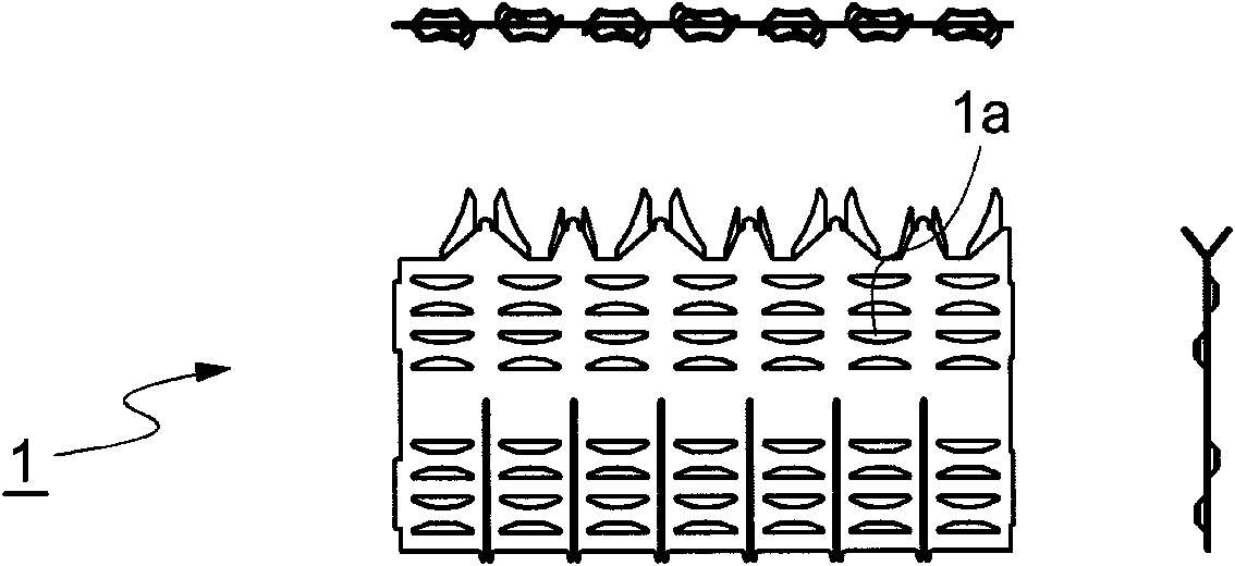
technical field [0001] The invention relates to a stamping device for inner strips. Background technique [0002] A grid is used to properly maintain the interval between fuel rods in the nuclear reactor core, to suppress the vibration of the rods, to support the fuel rods in the axial direction, and to restrain the rods in the vertical direction for the longitudinal movement. One type of common grid design is as follows: comprising a plurality of inner strips which together form an egg-basket type (egg-basket) having roughly square cells each containing fuel rods. crate). [0003] Such an inner strap (1) is formed into a desired pattern by stamping a metal sheet. The inner strip is not limited to a specific shape, such as figure 1 , 2 , As shown in 3, various shapes are formed, so there is a problem that a corresponding press equipment should be provided. [0004] Specifically, in stamping forming has such as figure 1 When the inner strip 1 of the pattern shown, the A...

Claims


Application Information

Patent Timeline
Patent Type & Authority Applications(China)
IPC IPC(8): B21D53/14B21D37/02
Inventor 李仁载
Owner JIN YOUNG PRECISION MACHINE
Learn More