
Screen printing plate and manufacturing method thereof

A technology for screen printing plates and manufacturing methods, which is applied to screen printing machines, printing machines, printing machines, etc., and can solve problems such as misalignment, increased manufacturing costs of screen printing plates, and lengthened plate-making processes

Active Publication Date: 2013-11-20
MURATA MFG CO LTD
View PDF6 Cites 0 Cited by
  • Summary
  • Abstract
  • Description
  • Claims
  • Application Information

AI Technical Summary

Problems solved by technology

[0007] However, the screen printing plate of Patent Document 1 has the advantage of sticking the alignment mark processed with the metal plate or the alignment mark processed with the screen mesh of the sheet on the upper surface and the lower surface of the outer yarn of the screen body of the combined structure. It is easy to cause relative misalignment between the printed pattern formed on the inner yarn and the alignment mark formed on the outer yarn
In addition, since it is necessary to additionally process this alignment mark, and to paste the alignment mark at the correct position on the upper or lower surface of the outer yarn, a device and a process, the plate-making process becomes longer and becomes a screen printing plate. The main reason for the increase in manufacturing cost of

Method used


Image

  • Screen printing plate and manufacturing method thereof
  • Screen printing plate and manufacturing method thereof
  • Screen printing plate and manufacturing method thereof

Examples


Embodiment Construction

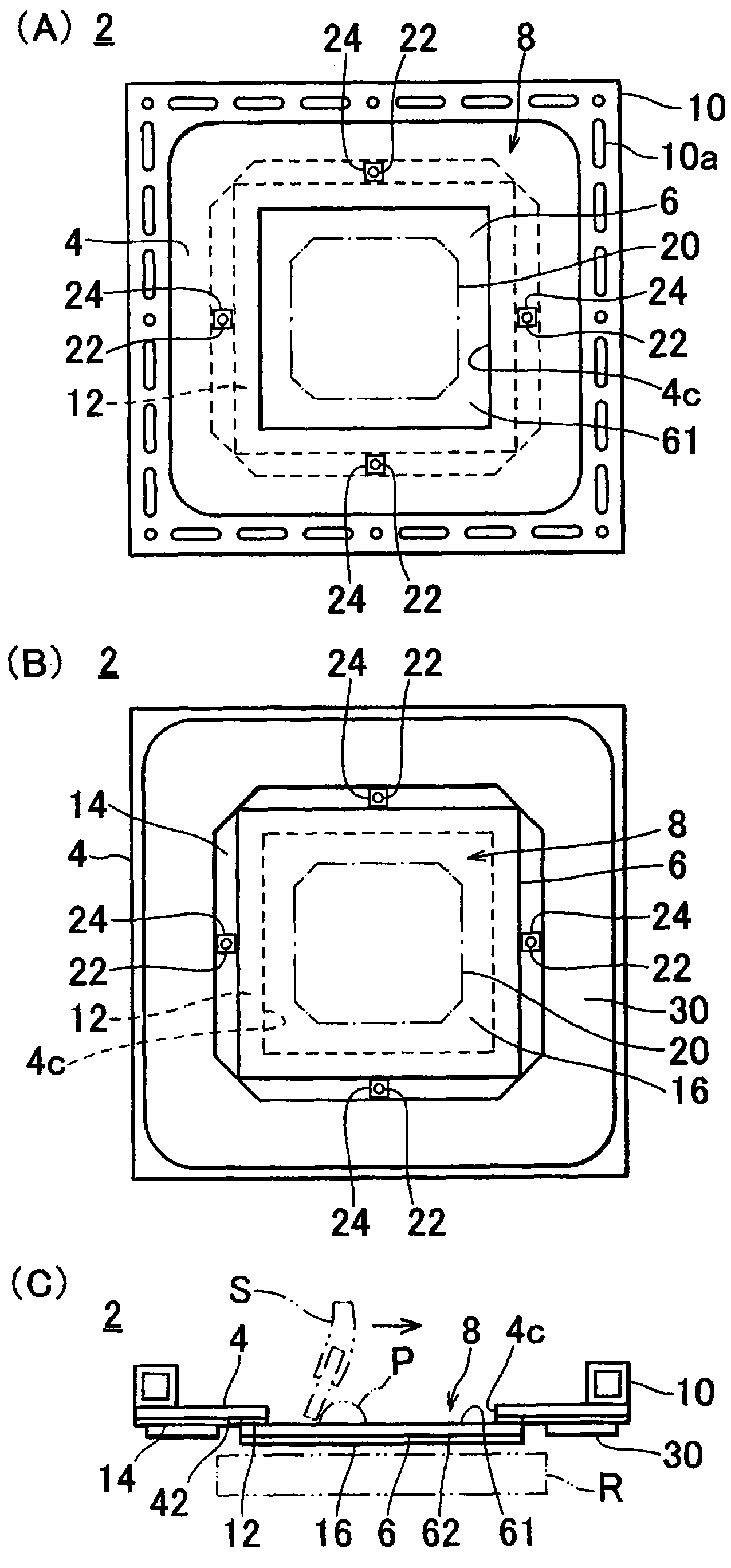
[0034] One embodiment of the screen printing plate of the present invention will be described. figure 1 (A) is a plan view showing the screen printing plate 2, figure 1 (B) is the rear view, figure 1 (C) is a schematic process diagram. The screen printing plate 2 basically includes: a screen body 8 having a combined structure of an outer yarn 4 and an inner yarn 6 ; and a frame 10 in the form of a picture frame.

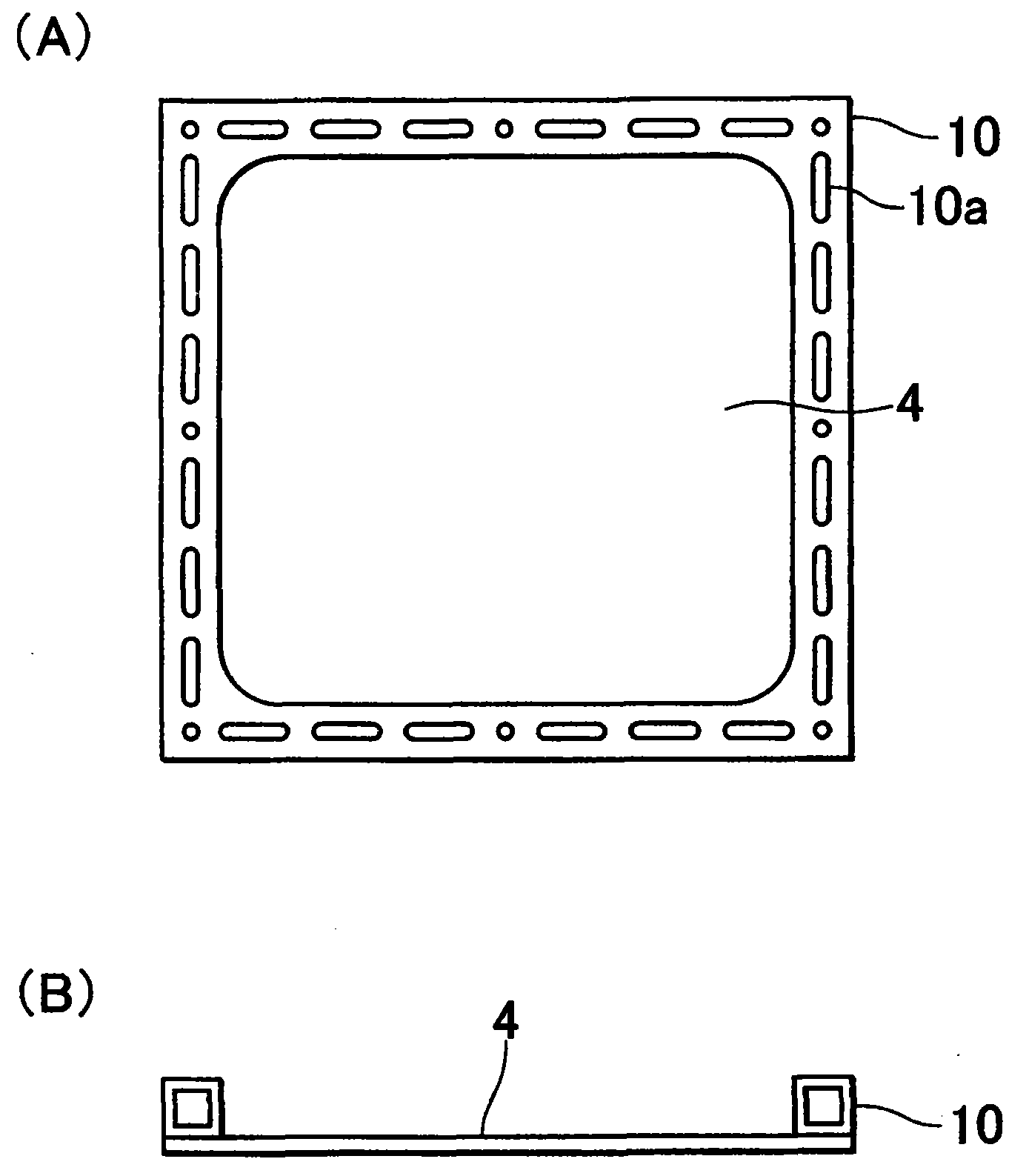
[0035] The picture frame-like frame 10 whose overall shape is rectangular is made of aluminum or stainless steel, and has a rectangular cylindrical cross-section to reduce weight and mechanical deformation, and has long holes 10a formed at predetermined intervals.

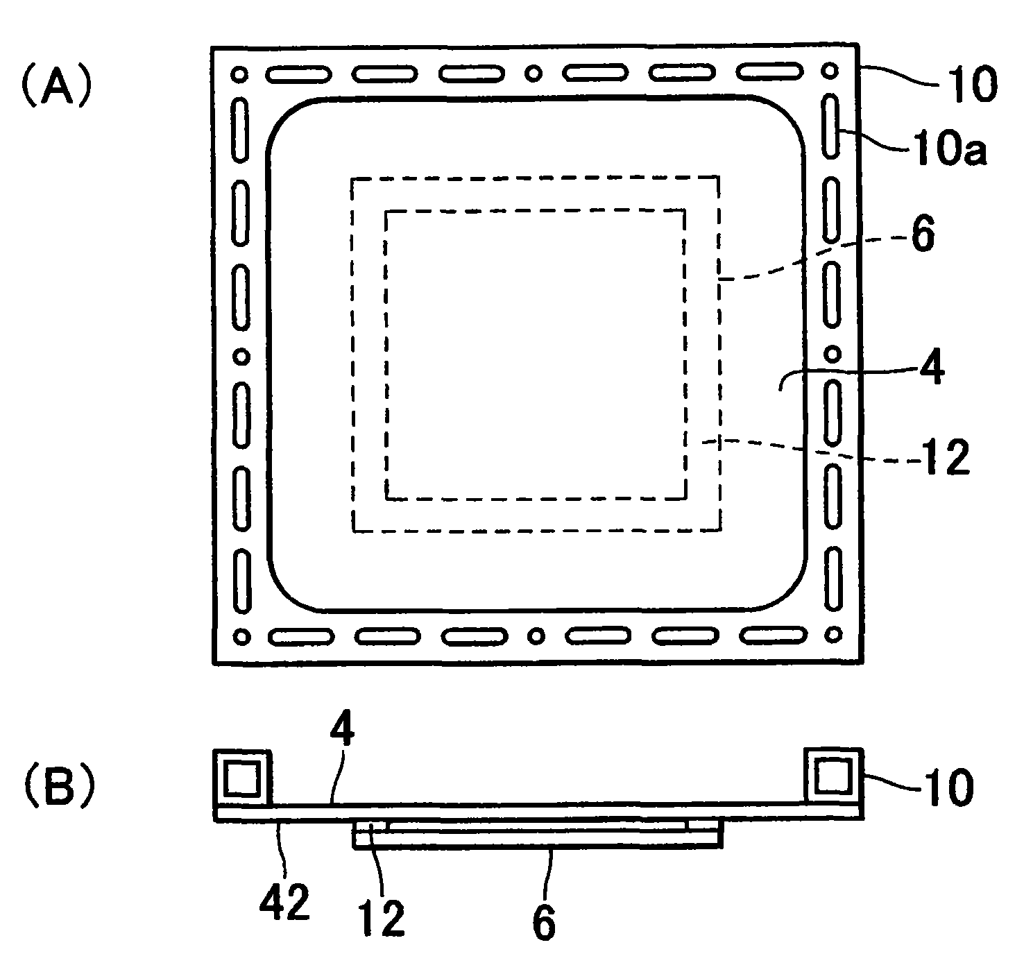
[0036] The outer yarn 4 is composed of a rectangular resin net, and is bonded with an adhesive by a normal (Nomal) pasting method (a method in which the fiber direction of the pasted resin net is parallel to the direction of the picture frame stencil 10 and pasted). Paste directly on the picture fra...


PUM


Abstract

The invention provides a screen printing plate and a manufacturing method thereof. The screen printing plate (2) comprises an outer yarn (4) of an opening part (4c) made of resin net; an inner yarn (6) matched with the outer yarn (4) of the opening part (4c) and made of metal net; an emulsion layer (16) for printed patterns made of phototonus resin and formed with printed patterns (20) on the inner yarn (6); an emulsion layer (14) for alignment marks made of phototonus resin and formed with alignment marks (22) on the outer yarn (4). The printed patterns (20) and the alignment marks (22) being separated by a photo mask (F) are formed by exposing and developing the emulsion layer (16) for printed patterns and the emulsion layer (14) for alignment marks. Therefore, the relative displacement between the printed patterns of the inner yarn and the alignment marks of the outer yarn is avoided and the manufacturing cost is low.

Description

technical field [0001] The invention relates to a screen printing plate used in screen printing and a manufacturing method thereof. Background technique [0002] Conventionally, a screen printing method is used as a method of printing an electrode pattern of an electronic component such as a solar cell or a protective film pattern of a portion other than the electrode pattern. In addition, in the screen printing method, a screen printing plate produced by applying a photosensitive emulsion to a screen such as stainless steel, exposing it, and developing it is used. In this screen printing plate, in addition to a printing pattern corresponding to the object to be printed, an alignment mark (araiment mark) for aligning the position of the object to be printed and the screen printing plate may be formed. In addition, the alignment marks are required to be placed as close as possible to the frame (forehead)-shaped frame of the screen printing plate in order to ensure a large pr...

Claims


Application Information

Patent Timeline
Patent Type & Authority Patents(China)
IPC IPC(8): B41F15/36B41C1/14
Inventor 山名毅吉田幸治
Owner MURATA MFG CO LTD
Learn More