Steel bar and joint of steel bar

A technology of steel bars and reinforced concrete, applied in the direction of structural elements, building components, building reinforcements, etc., to achieve the effect of suppressing interference and low height

Inactive Publication Date: 2011-10-12
DAI ICHI HIGH FREQUENCY
View PDF1 Cites 6 Cited by
  • Summary
  • Abstract
  • Description
  • Claims
  • Application Information

AI Technical Summary

Problems solved by technology

[0006] However, in conventional threaded joints, since a threaded portion having an enlarged diameter compared with the steel bar body is formed at the end of the steel bar, if the axial length and / or diameter of the threaded portion are large, the There is a possibility that the connecting tool that the threaded part is screwed may interfere with reinforcements other than the main reinforcements arranged around the reinforcements.

Method used


Image

  • Steel bar and joint of steel bar
  • Steel bar and joint of steel bar
  • Steel bar and joint of steel bar

Examples


Embodiment Construction

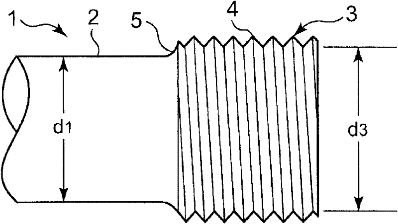
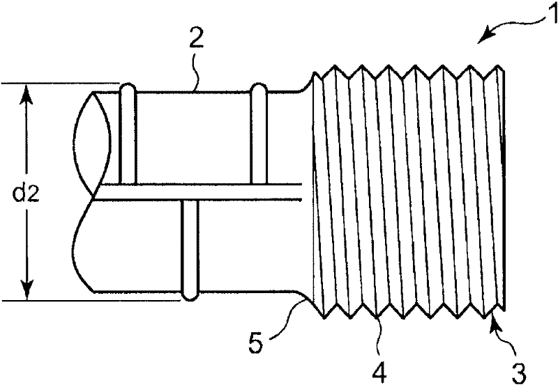
[0025] Next, one embodiment of a reinforcing bar and a reinforcing bar joint in the present invention will be described based on the drawings. Such as figure 1 As shown, the steel bar 1 of an example of this embodiment is used as the main bar of the beam or column which becomes a reinforced concrete, and the threaded part 3 is formed in the end part. That is, the reinforcing bar 1 of this embodiment is provided with the reinforcing bar main body 2 and the threaded part 3 . The steel bar 1 (that is, the steel bar body 2) is not particularly limited as long as it is used as the main bar of a reinforced concrete beam or column. (The common name of the steel bar is D25), the diameter is 28.6mm (the common name of the steel bar is D29), the diameter is 31.8mm (the common name of the steel bar is D32), the diameter is 34.9mm (the common name of the steel bar is D35), the diameter is 38.1mm (the common name of the steel bar is D38) ), steel bars with a diameter of 41.3mm (commonly ...


PUM


Abstract

The invention provides a steel bar capable of suppressing the interference of reinforcing steel bars. The steel bar (1) is used as the main reinforcement of steel bar concrete and the diameter of the end of the steel bar is expanded compared with the diameter of the steel bar body (2). The outer periphery of the steel bar is formed with the thread portion (3) of a male screw (4). The thread number of the male screw (4) is 6-9. The ratio (d3/d1) of the small-diameter of the male screw (4) to the diameter of the steel bar body (2) is 1.05-1.50. The corner (5) at the edge of the thread portion (3) with the steel bar body (2) is preferably formed to be round. In addition, a round corner is formed by the die forging of the thread portion (3) formed by the diameter expanding of the end of the steel bar compared with the steel bar body (2). The diameter of the round corner is preferably to be 1-3 times of that of the pitch of the male screw (4).

Description

technical field [0001] The present invention relates to a steel bar and a steel bar joint used as main bars (main iron bars) of reinforced concrete. Background technique [0002] In reinforced concrete, in order to make the steel bar of the limited standard length as the main bar become a continuous bar on site, a bar joint is used. As a steel bar joint, it is generally a lap joint or a pressurized gas welded joint that makes the steel bar coincide with a specified length; the lap joint makes the structure of the steel bar configuration complicated due to the overlap, and the quality of the pressurized gas welded joint is determined by the technology of the crimping worker. Such a disadvantage. [0003] Therefore, as a special joint, a joint in which cement slurry is injected into the sleeve together with the reinforcement has been developed. This special joint for injecting grout is preferable in terms of simplification of the reinforcement structure and put into practica...

Claims


Application Information

Patent Timeline
Patent Type & Authority Applications(China)
IPC IPC(8): E04C5/02E04C5/16
Inventor 岸原重树友田勇真田英人大和田丰胁山广三福田章
Owner DAI ICHI HIGH FREQUENCY
Why Eureka
Try Eureka