Improved method for designing smooth limit gauge

A technology of limit gauge and design method, applied in measuring gauges, ring gauges, measuring devices, etc., can solve the problems of reducing the proportion of qualified products of workpieces and judging waste, and achieve the effect of increasing the proportion of qualified products and obvious advantages.

Inactive Publication Date: 2011-10-12
CITIC DICASTAL
View PDF0 Cites 2 Cited by
  • Summary
  • Abstract
  • Description
  • Claims
  • Application Information

AI Technical Summary

Problems solved by technology

Although this reduces the manufacturing difficulty of the gauge, it makes some products that should be qualified be rejected, reducing the proportion of qualified workpieces

Method used


Image

  • Improved method for designing smooth limit gauge
  • Improved method for designing smooth limit gauge
  • Improved method for designing smooth limit gauge

Examples


Embodiment Construction

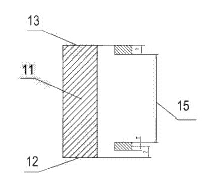
[0031] The technical solution of the present invention is: determine the manufacturing precision T of the gauge at IT2~IT4, reduce the percentage of the tolerance zone of the gauge relative to the tolerance zone of the workpiece, the position element Z determines the service life of the through end of the gauge, and the purpose is to pre-set Leave a wear limit. exist image 3 Among them, the ultimate meaning of the position element Z is to determine the distance between the drop of the gauge end and the maximum physical size of the workpiece to be measured, and the distance can be expressed by the formula Z+T / 2. The value range of Z+T / 2 is 0.0016~0.002.

[0032] Table 3 is a comparison between the design method of the prior art and the improved smooth limit through-gauge design method of the present invention when applied to different workpieces.

[0033] Table 3 List of calculation methods before and after the smooth limit gauge for holes.

[0034]

[0035] In Table 3, ...


PUM


Abstract

The invention discloses an improved method for designing a smooth limit gauge. The method is characterized by determining the manufacturing tolerance accuracy T of the gauge to be IT2-IT4; and reducing the percentage of a gauge tolerance zone relative to a workpiece tolerance zone, wherein the distance between the gauge go-end lower difference and the maximal physical dimension of a workpiece to be measured is expressed by a formula (Z+T/2), and the value range of the (Z+T/2) is from 0.0016 to 0.002.

Description

technical field [0001] The invention relates to a design method of a gauge, in particular to an improved design method of a smooth limit gauge. Background technique [0002] In mechanical manufacturing, whether the shaft diameter and aperture of the workpiece meet the specified technical requirements can be measured by general measuring instruments (such as calipers), measuring instruments (such as three-coordinate measuring machine), and can also be inspected by smooth limit gauges. Such as figure 1 / figure 2 As shown in , the smooth limit gauge is a special inspection tool without scale, which is designed and manufactured for the convenience of checking product quality. Because of its simple structure, easy manufacturing, time-saving and labor-saving measurement, and the ability to ensure the interchangeability of workpieces in production, it is widely used in mass production. When inspecting a part with a smooth limit gauge, it can only be judged whether the part is ...

Claims


Application Information

Patent Timeline
Patent Type & Authority Applications(China)
IPC IPC(8): G01B3/00
CPCG01B3/00G01B3/34
Inventor 郭建东
Owner CITIC DICASTAL
Why Eureka
Try Eureka