Supercharge Your Innovation With Domain-Expert AI Agents!

Non-conductor contact electric energy transmission device

A technology for contacting electric energy and transmission devices, which is applied in the direction of circuits, inductors, electrical components, etc., and can solve the problems of low power transmission efficiency, large magnetic flux leakage, and high cost

Inactive Publication Date: 2011-10-12
姬志强
View PDF7 Cites 10 Cited by
  • Summary
  • Abstract
  • Description
  • Claims
  • Application Information

AI Technical Summary

Problems solved by technology

The non-contact power transmission technology adopts a transformer with primary and secondary separation that relies on electromagnetic induction coupling to transmit energy. To a certain extent, the non-contact power transmission technology can meet certain occasions in special industries such as chemical industry, drilling, mining, and underwater detection. The use of electrical equipment under feed restrictions, but the magnetic flux leakage is large, the cost is high, and the efficiency is low. The online edition of "Guangming Daily" reported the news "Breakthrough in Non-contact Power Transmission Technology" at 07:39 on February 8, 2007. According to In the report, three invention patents have been applied for the research and development device. Its power output and transmission efficiency is 70%, which can still meet the requirements in some environments where the power consumption efficiency is not high, such as household power consumption, but in many conditions with high power consumption efficiency. Under this kind of power transmission efficiency is obviously low, and the manufacturing cost is too high

Method used


Image

  • Non-conductor contact electric energy transmission device
  • Non-conductor contact electric energy transmission device

Examples


Embodiment Construction

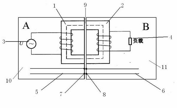
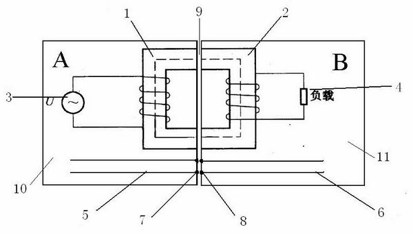
[0011] As shown in the figure, the non-conductor contact power transmission device includes a power supply terminal A and a power consumption terminal B. The power supply terminal A includes a "[" or "E"-shaped power supply terminal magnetic core 1 and a magnetic core 1 wound on the power supply terminal magnetic core 1. The primary coil and the AC power supply 3 connected to both ends of the primary coil, the power consumption terminal B includes a "]" or reverse "E"-shaped power consumption terminal magnetic core 2 and a secondary coil wound on the power consumption terminal magnetic core 2 and connected After the load 4 at both ends of the secondary coil, the power supply terminal A and the power consumption terminal B are combined, the magnetic core 1 of the power supply terminal and the magnetic core 2 of the power consumption terminal form an approximately complete "mouth"-shaped or "day"-shaped magnetic core, and the power supply terminal The magnetic core 1 and the powe...


PUM


Abstract

The invention discloses a non-conductor contact electric energy transmission device which comprises a power supply terminal and a power utilization terminal, wherein the power supply terminal comprises a '['-shaped or 'E'-shaped power supply terminal magnetic core, a primary coil and alternating power supplies; the primary coil is wound on the power supply terminal magnetic core; the alternating power supplies are connected at two ends of the primary coil; the power utilization terminal comprises a ']'-shaped or a reverse 'E'-shaped power utilization terminal magnetic core, a secondary coil and loads; the secondary coil is wound on the power utilization terminal magnetic core; the loads are connected to the two ends of the secondary coil; after the power supply terminal and the power utilization terminal are combined, the power supply terminal magnetic core and the power utilization terminal core form an approximate complete 'square'-shaped magnetic core or a magnetic core in the shape of a Chinese character 'ri'; and the power supply terminal magnetic core and the power utilization terminal core form an enclosed magnetic line of force channel. The non-conductor contact electric energy transmission device has the advantages of less magnetic leakage, low cost and high efficiency.

Description

technical field [0001] The invention relates to a power transmission device, in particular to a non-conductor contact power transmission device. Background technique [0002] At present, there are currently two solutions for applications that require power transmission. The first widely used is the primary and secondary integrated transformer, which can be used for voltage transformation or isolation. This method is used when replacing the load. , easy to spark, does not meet the requirements of safety production regulations, and seriously endangers safety production. The second type is a transformer for non-contact charging and a rechargeable electric appliance device, that is, a separate transformer. Its manufacturing and research are currently mainly in the stage of theory and a small amount of experimental research. The non-contact power transmission technology adopts a transformer with primary and secondary separation that relies on electromagnetic induction coupling ...

Claims


Application Information

Patent Timeline
Patent Type & Authority Applications(China)
IPC IPC(8): H02M5/10H01F38/14
Inventor 姬志刚曹志强贾海亮王亚涛姬志强
Owner 姬志强
Features
  • R&D
  • Intellectual Property
  • Life Sciences
  • Materials
  • Tech Scout
  • Unparalleled Data Quality
  • Higher Quality Content
  • 60% Fewer Hallucinations
Learn More