Clamp for assembling one-way clutch

A one-way clutch and fixture technology, which is applied in the direction of manufacturing tools and workpiece clamping devices, can solve the problems of damage to the function of the one-way clutch, complicated assembly operations, etc., and achieve the effect of easy assembly, rapid assembly, and realization of assembly

Active Publication Date: 2011-10-19
JATCO LTD
View PDF8 Cites 0 Cited by
  • Summary
  • Abstract
  • Description
  • Claims
  • Application Information

AI Technical Summary

Problems solved by technology

[0011] However, in this case, if Image 6 As shown by the dotted line in (b), the strut 102 is assembled in a state of being tilted to a large extent, thereby, the inner ring R 1 with outer ring R 2 Locked (fixed) between them, impairing the original function of the one-way clutch
Moreover, in order to eliminate such problems, troublesome assembly work is required only in manual work

Method used


Image

  • Clamp for assembling one-way clutch
  • Clamp for assembling one-way clutch
  • Clamp for assembling one-way clutch

Examples


Embodiment Construction

[0059] Hereinafter, one embodiment of the jig for assembling a one-way clutch according to the present invention will be described in detail with reference to the drawings.

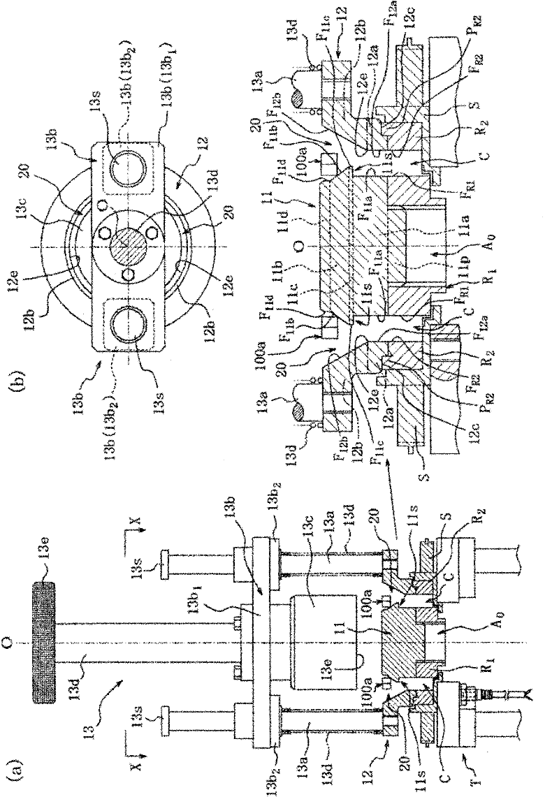
[0060] Such as Figure 6 , 7 As shown in the example, the one-way clutch 100 of this embodiment is used for the stator S of the torque converter. Inner ring R 1 The worm gear is spline-fitted via the spline hole formed inside it, and the outer member R 2 is fixed on the stator S. Thus, the one-way clutch 100 connects the drive shaft and the stator S and rotates them integrally until the drive shaft reaches a certain rotation, thereby enhancing the torque converter function and When the rotation speed of the drive shaft reaches a certain value or more, the connection between the drive shaft and the stator S is released to idle the stator S, thereby preventing the torque increase function from being degraded due to the increase in the rotation of the drive shaft.

[0061] In the figure T is assembled on...


PUM


Abstract

A clamp for assembling a one-way clutch assembles no clutches when a diagonal brace of an intermediate body is abnormal and can maintain the original functions of the one-way clutch and achieve rapid and easy assembly. The one-way clutch in the invention is formed by equipping the intermediate body on a circular gap formed between an internal piece and an external piece. The intermediate body maintains the diagonal brace and makes the diagonal brace capable of swinging respectively through elastic pieces on opening parts formed in a way separated along the circumference of circular parts. The one-way clutch assembling clamp comprises an inside base station connected with the end of the internal piece and an outside base station connected with the end of the external piece. The inside base station and the outside base station respectively form a circular through path having a circular end opening part inserting the intermediate body between the inside base station and the outside base station and guiding the intermediate body towards the gap through the end opening part. Furthermore, the external circumferential side of the outside base station is provided with an inclining part for pushing out the diagonal brace through resisting elastic force formed when the intermediate body enters the through path. An inclining part for pushing back the diagonal brace towards the elastic force direction when the intermediate body enters the through path is equipped on the outside base station. A step is formed on the inclining part for pushing out. When the diagonal brace is oriented by the space formed through the step, the intermediate body is then guided towards the gap.

Description

technical field [0001] The present invention relates to a jig for assembling a one-way clutch in which an intermediate body is disposed in an annular gap formed between an inner member and an outer member, and the intermediate body is spaced at intervals along the circumferential direction of the annular member. The formed openings respectively hold the braces via the elastic pieces and make them swingable. Background technique [0002] As a conventional one-way clutch, for example, a one-way clutch employed in a stator of a torque converter, a clutch formed by being held between an inner ring and an outer ring is known (for example, refer to Patent Document 1). [0003] Patent Document 1: (Japanese) Unexamined Patent Publication No. 4-73452 [0004] In contrast to this, in recent years, a one-way clutch in which a plurality of sprags are elastically held to an opening of an annular member in a swingable manner has been proposed. In such a one-way clutch, an intermediate b...

Claims


Application Information

Patent Timeline
IPC IPC(8): B25B11/02
Inventor 田村清人金森义幸篠原史明
Owner JATCO LTD
Why Eureka
Try Eureka