Engine combined brake control method

An engine braking and combined braking technology, applied in engine control, engine components, machine/engine, etc., can solve problems such as complex structure of engine braking system, optimize braking power, simplify braking system, and reduce costs Effect

Active Publication Date: 2011-10-19
SHANGHAI UNIVERSOON AUTOPARTS CO LTD
View PDF6 Cites 19 Cited by
  • Summary
  • Abstract
  • Description
  • Claims
  • Application Information

AI Technical Summary

Problems solved by technology

[0009] The object of the present invention is to provide a combined engine braking control method, which solves the problem of engine braking using variable exhaust butterfly valve brakes or pressure relief exhaust butterfly valves in the prior art. Technical issues with complex system structures

Method used


Image

  • Engine combined brake control method
  • Engine combined brake control method
  • Engine combined brake control method

Examples


Embodiment 1

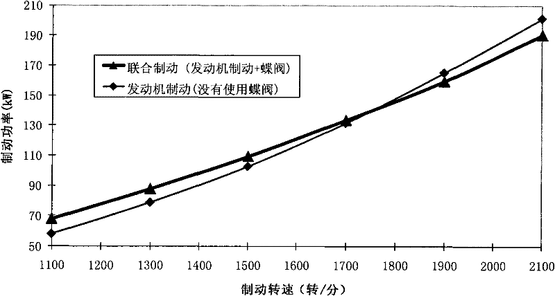
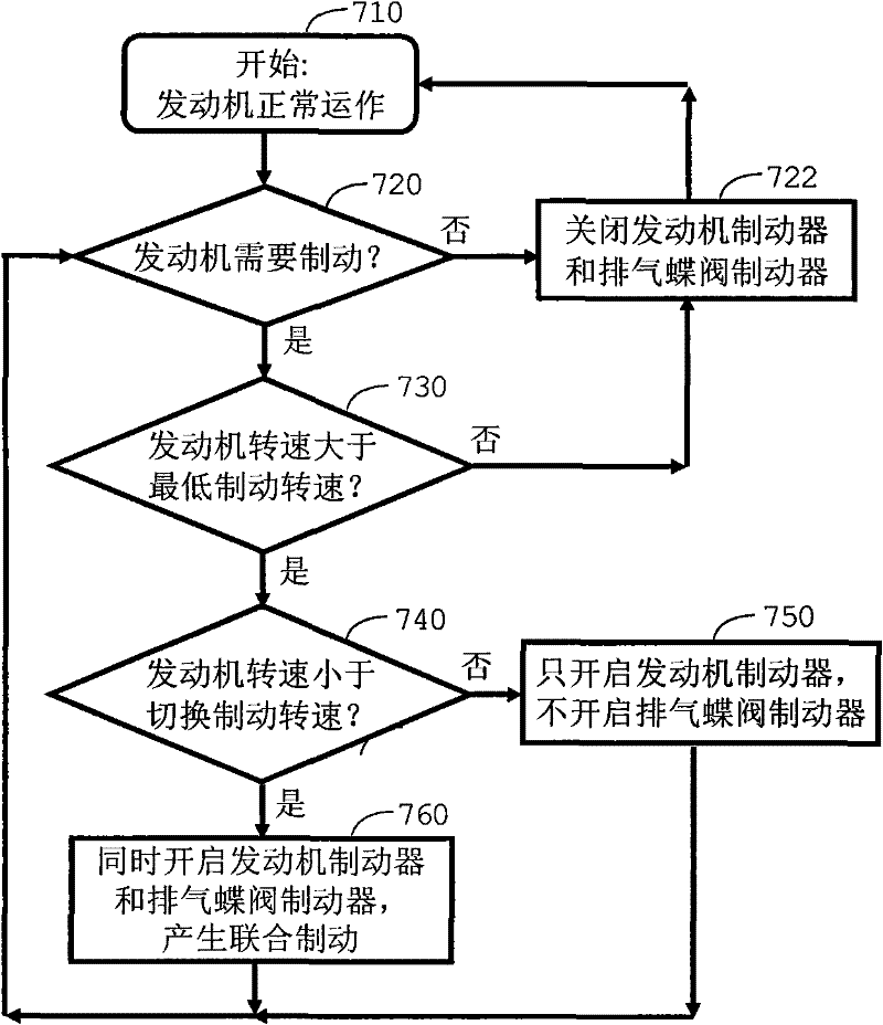
[0023] The engine combined braking control method of the present invention includes a step of controlling the action process of the engine brake and a step of controlling the action process of the exhaust butterfly valve brake, the engine brake is arranged on an engine, and the exhaust butterfly valve brake It is arranged in the exhaust system of the engine, wherein, in the step of controlling the action process of the engine brake and the step of controlling the action process of the exhaust butterfly valve brake, the braking speed of the engine is detected, and at the same time Compare the braking speed of the engine with a switching braking speed. When the braking speed of the engine is lower than the switching braking speed, the engine brake and the exhaust butterfly valve brake are activated. When the braking speed of the engine is higher than or When equal to switching brake speed, activate the engine brake and keep the exhaust butterfly valve brake closed.

[0024] Furt...


PUM


Abstract

The invention relates to an engine combined brake control method which comprises the steps of controlling the action process of an engine brake and controlling the action process of an exhaust butterfly valve brake. The engine brake is arranged on an engine, and the exhaust butterfly valve brake is arranged in an exhaust system of the engine. The braking speed of the engine is detected, and the braking speed of the engine is compared with one switching braking speed. When the braking speed of the engine is lower than the switching braking speed, the engine brake and the exhaust butterfly valve brake are started. When the braking speed of the engine is higher than or equal to the switching braking speed, the engine brake is started, and the exhaust butterfly valve brake is remained to be closed. According to the engine combined brake control method disclosed by the invention, the optimization of braking power and the safe operation of the engine are realized, no complex and expensive variable exhaust butterfly valve brake or pressure relief exhaust butterfly valve brake is needed to control the exhaust back pressure of the engine, the braking system is simplified, and the cost is reduced.

Description

Technical field: [0001] The invention relates to the field of automobiles, in particular to the braking control of an automobile engine, in particular to an engine combined braking control method. Background technique: [0002] In the prior art, the internal combustion engine is often used as a braking means, which is realized by temporarily converting the engine into a compressor. This transition cuts off fuel and opens the exhaust valve at or near the end of the engine piston's compression stroke, allowing the compressed gas (air during braking) to be released. The energy absorbed by the engine during the compression stroke cannot Returns to the engine piston during the subsequent expansion stroke, but is dissipated through the engine's exhaust and cooling system. The end result is effective engine braking that slows the vehicle. [0003] Engine braking is divided into two categories: compression release engine braking and deflated engine braking. [0004] A conventiona...

Claims


Application Information

Patent Timeline
IPC IPC(8): F02D13/02F02D9/06F01L13/06
CPCF02D9/06F02D13/04
Inventor 杨洲
Owner SHANGHAI UNIVERSOON AUTOPARTS CO LTD
Why Eureka
Try Eureka