
Air purifier and air treatment method thereof

An air purifier and air treatment technology, which is applied in the direction of control input, instruments, and heating methods related to air characteristics, can solve the problem of being unable to detect the location of pollutants, and achieve the effect of shortening working time and achieving obvious results

Active Publication Date: 2011-10-19
ECOVACS ROBOTICS (SUZHOU ) CO LTD
View PDF4 Cites 22 Cited by
  • Summary
  • Abstract
  • Description
  • Claims
  • Application Information

AI Technical Summary

Problems solved by technology

[0005] However, the current air purifiers only passively remove the pollutants in the air, and they cannot detect the location of the pollutants, so that they cannot find the source of the pollutants, fundamentally solve the problems of air pollution and improve air quality

Method used


Image

  • Air purifier and air treatment method thereof
  • Air purifier and air treatment method thereof
  • Air purifier and air treatment method thereof

Examples


Embodiment 1

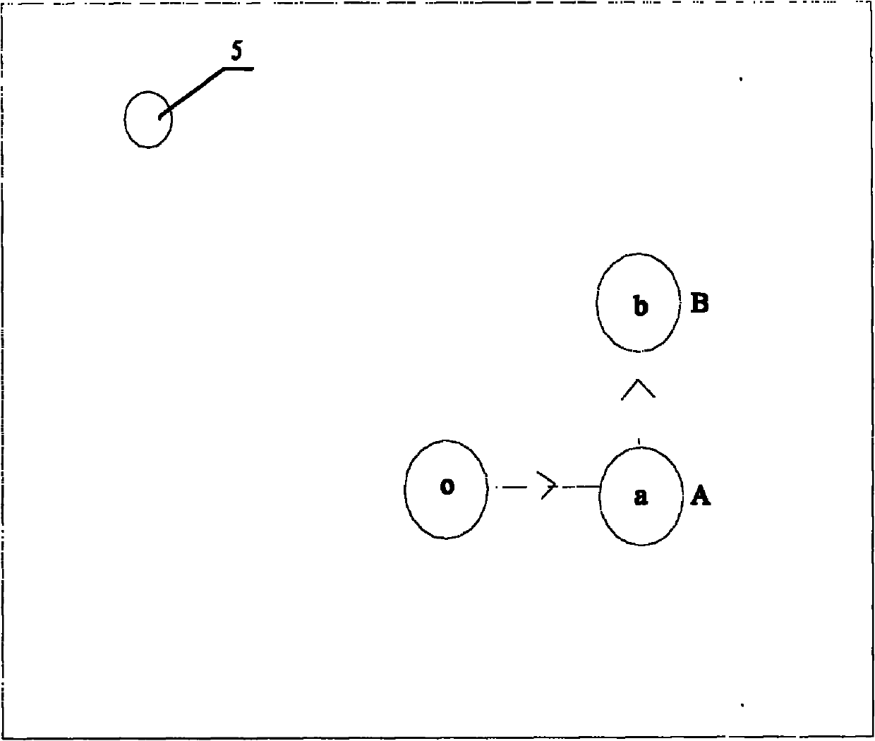
[0038] After the air purifier enters the cleaning mode, the mobile unit starts to go straight under the control of the control unit. Let the straight direction be the direction A, and the starting point of the movement in this direction is point o, such as figure 2 As shown, at the same time, the timer in the control unit starts timing, and the air quality sensor detects the air pollution information value at the same time. Once the walking time of the mobile unit reaches the preset time in the control unit, the control unit controls the mobile unit to stop moving. At this time, the air cleaner is located in the direction A, and at the end point a of the movement in this direction. The information storage subunit stores the air pollution information value A detected by the pollution detection sensor when the air purifier is respectively located at point o and point a o and A a . The control unit controls the mobile unit to rotate 90 degrees counterclockwise, so that the dir...

Embodiment 2

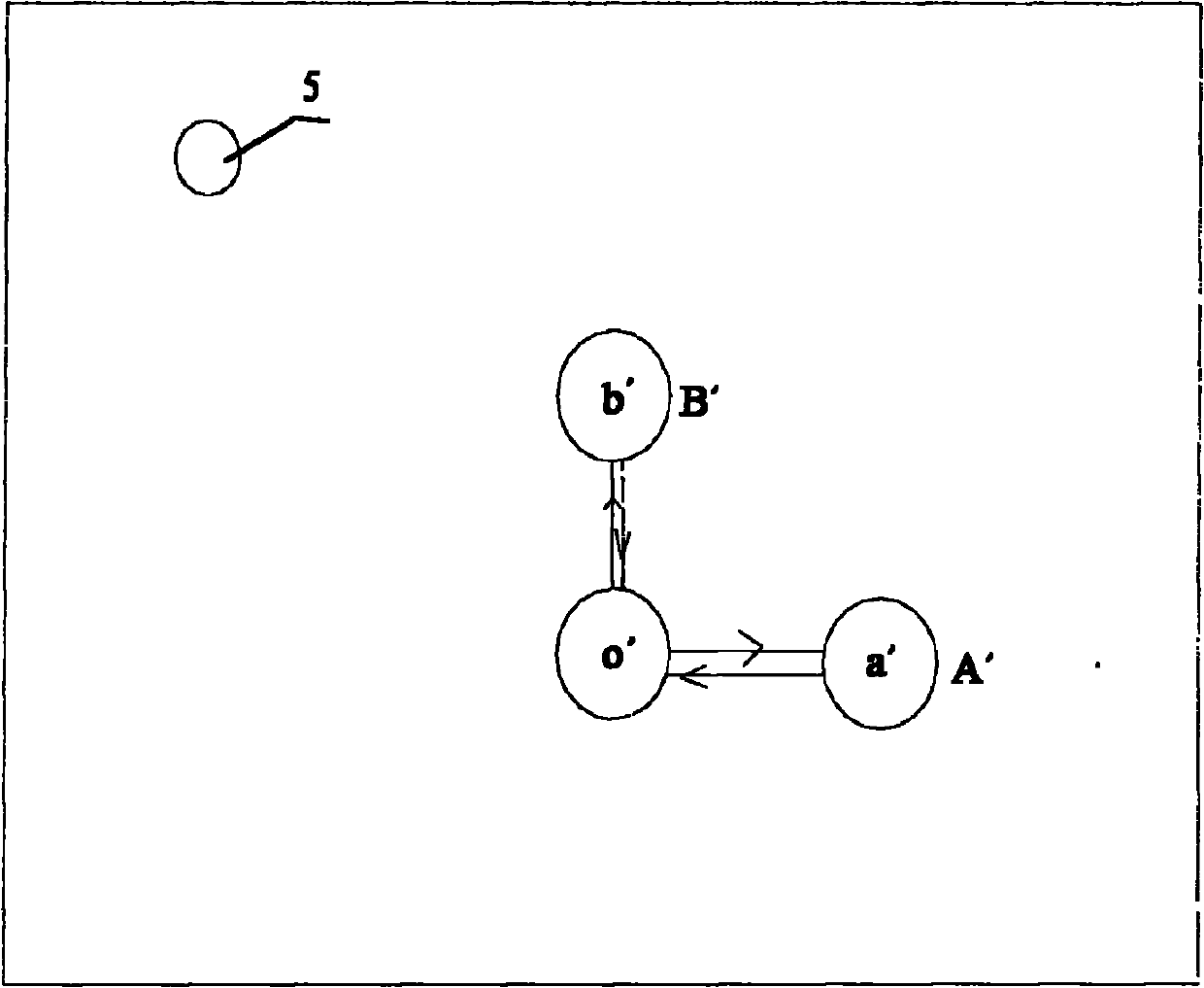
[0046] After the air purifier enters the cleaning mode, the mobile unit starts to go straight under the control of the control unit. Let the straight direction be the direction A', and the starting point of the movement in this direction is point o', such as image 3 As shown, at the same time, the timer in the control unit starts timing, and the air quality sensor detects the air pollution information value at the same time. When the time of the mobile unit 10' walking reaches the preset time in the control unit, the control unit controls the mobile unit to suspend the movement. At this time, the air cleaner is located in the direction A' and at the end point a' of the direction. The information storage subunit stores the air pollution information value A' detected by the air quality sensor when the air purifier is located at point o' and point a' respectively o1 and A' a1 . The control unit controls the mobile unit to rotate 180 degrees, so that the direction of the body o...


PUM


Abstract

The invention relates to an air purifier and an air treatment method thereof. The air purifier comprises an upper main body and a lower main body and is characterized in that an air treatment unit arranged in the upper main body is used for treating the air in the area to be treated; a moving unit arranged in the lower main body comprises a driving unit and a driving wheel; a control unit is used for respectively controlling the air treatment unit and the moving unit to work; an air quality sensor is used for detecting the information value of air pollution; the signal of the air quality sensor is transferred to the control unit; an information storage subunit in the control unit is used for storing the information value detected by the air quality sensor, of air pollution in the starting and finishing positions from and to which the air purifier goes straight in two different directions; and an information treatment subunit in the control unit is used for treating the information value stored in the information storage subunit, of air pollution and judging the direction of the pollution source. The air purifier and the air treatment method have the following beneficial effects: the air purifier purifies the pollution source from the source by actively seeking the pollution source, thus shortening the working time and achieving an obvious effect.

Description

technical field [0001] The invention belongs to the technical field of cleaning equipment, and in particular relates to an air purifier and an air treatment method thereof. Background technique [0002] The air purifier is a new type of household appliance, which has the functions of automatically detecting smoke, filtering dust, eliminating peculiar smell and harmful gas, and sterilizing. Air purifiers are usually composed of high-voltage generating circuits, negative ion generators, ventilators (micro fans), air filters and other systems. The indoor air is circulated through the ventilator in the air purifier, and the polluted air is filtered through the air filter in the machine to remove or absorb various pollutants, and then pass through the negative ion generator installed at the air outlet (negative ions are generated during operation) The high-voltage generating circuit in the device generates DC negative high voltage), continuously ionizes the air, generates a larg...

Claims


Application Information

Patent Timeline
Patent Type & Authority Applications(China)
IPC IPC(8): F24F11/00G01N33/00F24F3/16
CPCA61L9/00A61L2209/111F24F3/16F24F2221/125F24F2221/42F24F11/30F24F2110/50Y02B30/70
Inventor 汤进举
Owner ECOVACS ROBOTICS (SUZHOU ) CO LTD
Learn More