Raster scanning for depth detection

A raster scanning and detector technology, which is used in distance measurement, measurement device, line-of-sight measurement, etc., and can solve problems such as poor signal-to-noise ratio and depth that cannot be determined.

Active Publication Date: 2011-10-19
MICROSOFT TECH LICENSING LLC
View PDF7 Cites 21 Cited by
  • Summary
  • Abstract
  • Description
  • Claims
  • Application Information

AI Technical Summary

Problems solved by technology

Therefore, the signal-to-noise ratio (S/N) can be poor
Also, if a part of the object extends

Method used


Image

  • Raster scanning for depth detection
  • Raster scanning for depth detection
  • Raster scanning for depth detection

Examples


Embodiment Construction

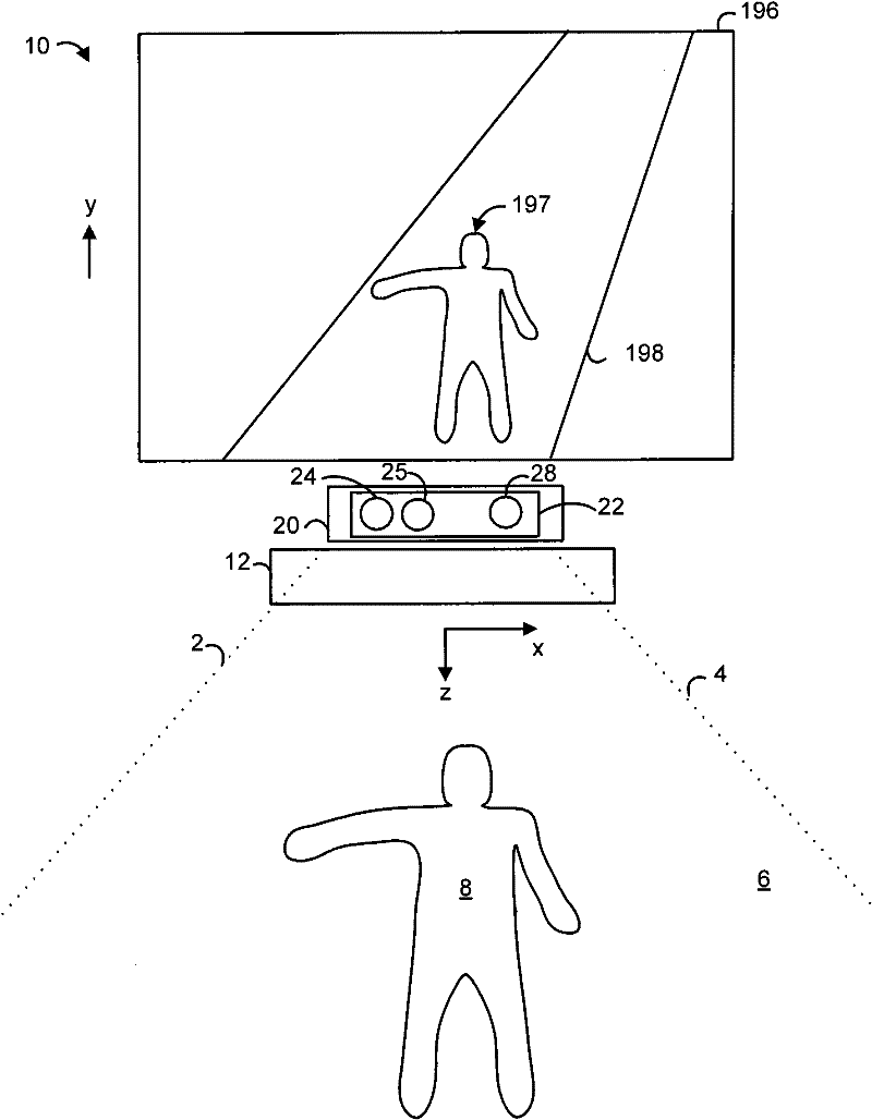
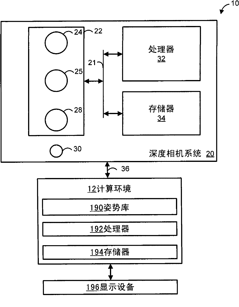
[0021] Techniques are provided for determining one or more distances to an object (or objects) within the field of view of a depth camera. Techniques may include raster scanning light on objects within the camera's field of view. An image of light reflected from the object is received at the camera. One or more distances to the object are determined based on the reflected image. In one embodiment, a 3D map of one or more objects within the field of view is generated.

[0022] In an embodiment, determining the distance(s) to the object includes determining a time-of-flight between sending light from a light source within the camera and receiving a reflected image from the object. Separate time-of-flight information can be determined for different points within the raster scan. Thus, a 3D mapping of the object can be determined.

[0023] In one embodiment, the raster scanning light includes a raster scanning pattern into the field of view. Determining the distance(s) to the...


PUM


Abstract

The invention provides raster scanning for depth detection. Techniques are provided for determining distance to an object in a depth camera's field of view. The techniques may include raster scanning light over the object and detecting reflected light from the object. One or more distances to the object may be determined based on the reflected image. A 3D mapping of the object may be generated. The distance(s) to the object may be determined based on times-of-flight between transmitting the light from a light source in the camera to receiving the reflected image from the object. Raster scanning the light may include raster scanning a pattern into the field of view. Determining the distance(s) to the object may include determining spatial differences between a reflected image of the pattern that is received at the camera and a reference pattern.

Description

technical field [0001] The present invention relates to depth detection, and more particularly to raster scanning for depth detection. Background technique [0002] A depth camera system obtains data related to the position of a person or other object within a physical space. This information may be referred to as "depth information". Depth information may be input to applications within the computing system for a variety of applications. There may be many applications such as for military, entertainment, sports and medical purposes. For example, depth information about a person can be mapped to a three-dimensional (3-D) human skeletal model and used to create an animated character or avatar. [0003] To determine depth information, a depth camera may project light onto objects within the camera's field of view. The light reflects off the subject and returns to the camera where it is processed to determine depth information. However, the intensity of the light reflected...

Claims


Application Information

Patent Timeline
IPC IPC(8): G06T7/00
CPCG01S7/4817G01S17/10G01S17/36G01S17/42G01S17/48G01S17/66G01S17/88G01S17/89G06T2207/30196G06T7/521G01C3/08
Inventor D·伊J·卢蒂安
Owner MICROSOFT TECH LICENSING LLC
Why Eureka
Try Eureka