Ejector sleeve device mechanism

A pipe groove and material trough technology is applied in the field of integrated circuit testing and sorting machines, which can solve the problems of unstable limit function of the push pipe device, partial replacement of the push pipe groove, and left and right shaking of the material pipe, so as to save the vertical direction. Space, manpower saving, and the effect of reducing manual intervention

Inactive Publication Date: 2011-10-19
HANGZHOU CHANGCHUAN TECH CO LTD
View PDF4 Cites 4 Cited by
  • Summary
  • Abstract
  • Description
  • Claims
  • Application Information

AI Technical Summary

Problems solved by technology

[0002] At present, there are many kinds of push tube device mechanisms used in integrated circuit testing and packaging. Among them, some push tube devices have unstable limit functions, and the material tube will shake from side to side. workload

Method used


Image

  • Ejector sleeve device mechanism
  • Ejector sleeve device mechanism
  • Ejector sleeve device mechanism

Examples


Embodiment Construction

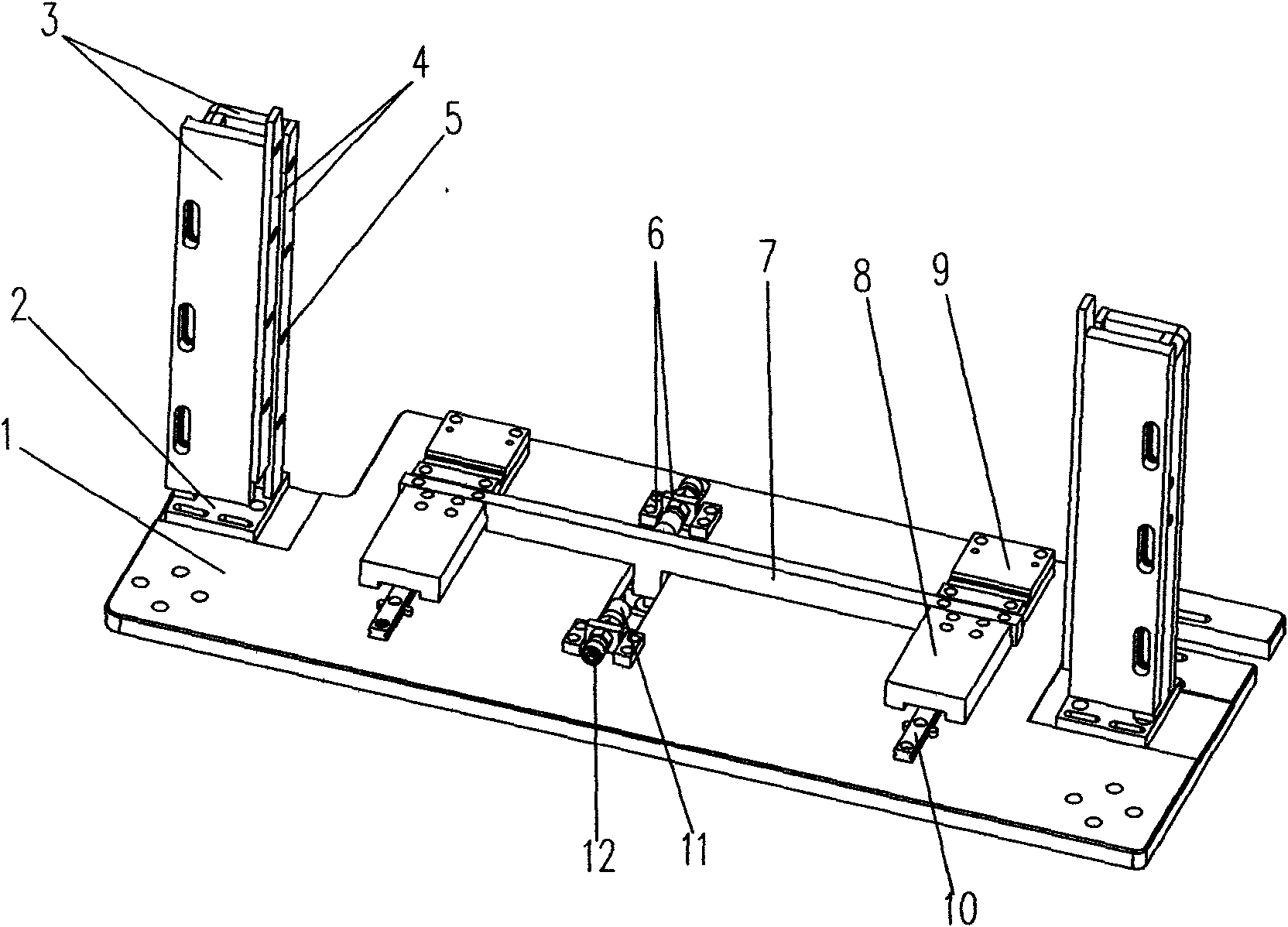
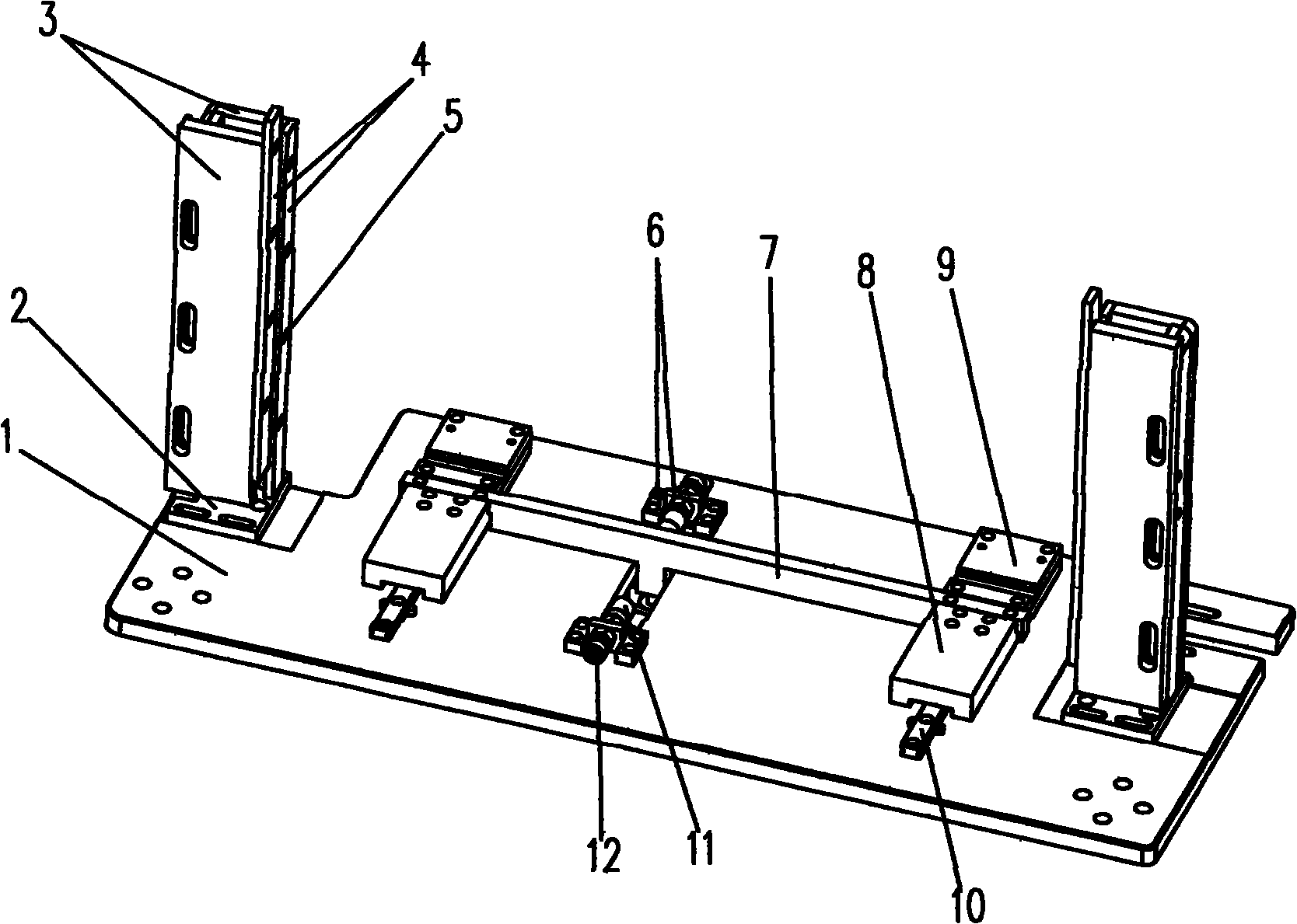
[0022] The present invention will be described in detail below in conjunction with the accompanying drawings: Figure 1-2 Shown: a pipe pushing device mechanism, which includes: a bottom plate 1;

[0023] A feeding mechanism and a tube pushing mechanism arranged on one side of the bottom plate 1; the two feeding slots 3 of the feeding mechanism are respectively arranged at both ends of the bottom plate 1; two sliding rails 10 of the tube pushing mechanism It is fixed in parallel between the two feeding troughs (3) on the bottom plate 1; the sliding rail 10 is fixed with two push tube groove fixing plates 8; the two push tube groove fixing plates (8 ) The connecting rod 7 of the pipe pushing device is embedded between;

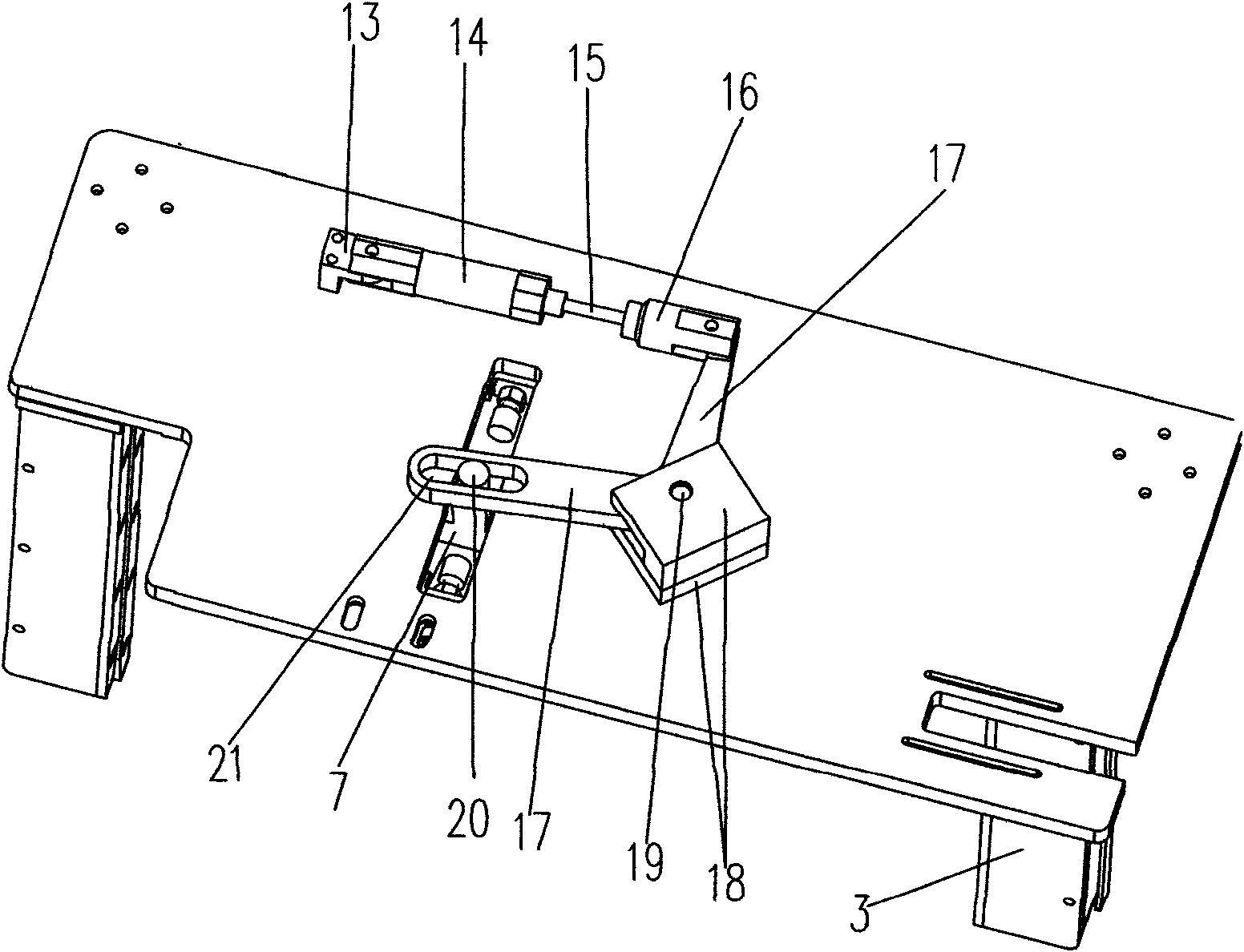
[0024] A driving device arranged on the other side of the bottom plate 1; one end of the cylinder block 14 of the driving device is connected to an L-shaped single elbow joint 13; the other end of the cylinder block 14 is connected to a cylinder piston rod 15; the ...


PUM


Abstract

An ejector sleeve device mechanism comprises a soleplate, a feeding mechanism and an ejector sleeve mechanism arranged on one side of the soleplate, and a driving device arranged on the other side of the soleplate. The ejector sleeve device mechanism is smart in structure and can be suitable for material tubes with relatively larger deformation, thereby being capable of efficiently reducing the manual intervention and saving the labor power.

Description

Technical field [0001] The invention relates to the technical field of an integrated circuit test sorting machine, in particular to a push tube device mechanism. Background technique [0002] At present, there are many kinds of push tube device mechanisms used in integrated circuit testing and packaging. Among them, some push tube devices have unstable limiting functions, and the material tube will sway from side to side. Some push tube slots cannot be replaced locally. The overall replacement is a waste of time and increases. Workload. Summary of the invention [0003] The purpose of the present invention is to overcome the above-mentioned shortcomings and provide a safe and stable pipe pushing device mechanism. [0004] The purpose of the present invention is accomplished through the following technical solutions, a pipe pushing device mechanism, which includes: [0005] A floor [0006] A feeding mechanism and a tube pushing mechanism arranged on one side of the bottom plate; the ...

Claims


Application Information

Patent Timeline
Patent Type & Authority Applications(China)
IPC IPC(8): H01L21/00H01L21/68B07C5/00
Inventor 韩笑
Owner HANGZHOU CHANGCHUAN TECH CO LTD
Why Eureka
Try Eureka