
Current source power supply circuit for weak current system

A technology of power supply circuit and weak current system, applied in the direction of converting irreversible AC power input to DC power output, electrical components, output power conversion devices, etc., can solve the problem of poor anti-interference ability, increased leakage inductance, unstable power supply, etc. problem, to achieve the effect of strong stability and strong isolation ability

Inactive Publication Date: 2011-10-19
杭州四达电炉成套设备有限公司
View PDF5 Cites 1 Cited by
  • Summary
  • Abstract
  • Description
  • Claims
  • Application Information

AI Technical Summary

Problems solved by technology

Voltage source power supply, poor anti-interference ability, the primary side of the voltage transformer is high-voltage power, the interference of the primary side will be coupled to the secondary side according to the ratio of the transformer, resulting in unstable power supply
The isolation capability of the voltage source and the load capacity are contradictory. In order to enhance the isolation capability, the thickness of the insulating layer between the primary and secondary sides is increased, which will cause an increase in the leakage inductance, resulting in a weakened load capacity of the voltage source.

Method used


Image

  • Current source power supply circuit for weak current system
  • Current source power supply circuit for weak current system

Examples


Embodiment Construction

[0010] The present invention will be further described below with reference to the accompanying drawings.

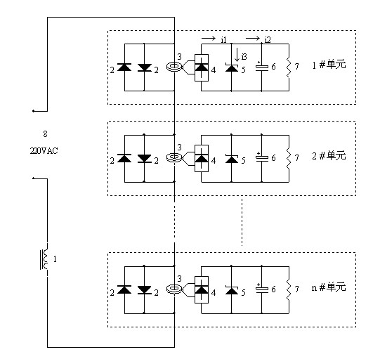
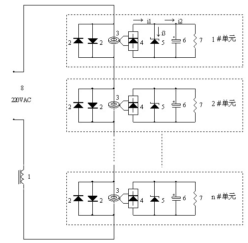
[0011] refer to figure 1 , the present invention includes adopting a current-stabilizing inductor 1, a current transformer 3 to isolate the output, and the primary sides of N current transformers 3 connected in series to form N groups of output units to supply power to the weak current system respectively. The secondary side of the current transformer 3 is composed of a rectifier bridge 4 , a voltage regulator tube 5 , a filter capacitor 6 and a load 7 . The voltage regulator tube 5 limits the amplitude and converts the current into voltage. The size of the rectifier bridge 5 and the filter capacitor 6 is determined by the load 7 . A diode 2 connected in parallel in forward and reverse directions is placed on the primary side of each current transformer 3 to prevent open-circuit overvoltage. The AC voltage 8 generates a stable current through the inductor 1 with large ...


PUM


Abstract

The invention relates to a current source power supply circuit for a weak current system. The conventional power supply technology for the weak current system mainly adopts a voltage source power supply mode. In the current source power supply circuit for the weak current system, primary sides of a plurality of current transformers are connected in series; one end of the first current transformer is connected with a 220V mains supply; one end of the last current transformer is connected with one end of a current-stabilizing inductor; the other end of the current-stabilizing inductor is connected with the 220V mains supply; the primary side of each current transformer is connected with a pair of diodes connected in parallel forwardly and reversely to prevent open-circuit over-voltage; a secondary side of each current transformer comprises a rectifier bridge, a voltage-stabilizing tube and a filter capacitor; a negative electrode of the voltage-stabilizing tube is connected with one output end of the rectifier bridge, and a positive electrode of the voltage-stabilizing tube is connected with the other output end of the rectifier bridge; and the positive electrode of the filter capacitor is connected with one output end of the rectifier bridge, and the negative electrode of the filter capacitor is connected with the other output end of the rectifier bridge. The current source power supply circuit for the weak current system is simple in structure and stable in output.

Description

technical field [0001] The invention relates to the technical field of power supply, in particular to a current source power supply circuit for a weak current system. Background technique [0002] The power supply technology of the weak current system can provide power supply for each load. The power supply technology of the existing weak current system mainly adopts the voltage source power supply mode, and the type of the voltage source can be the general grid voltage. The most common method of voltage source energy transmission is the power transformer method. The secondary side of the power transformer is prohibited from short-circuiting. When the secondary side of the voltage source is short-circuited, the current generated is very large, which causes a large amount of heat, which will burn the load or the transformer itself. . The voltage source power supply has poor anti-interference ability. The primary side of the voltage transformer uses high-voltage electricity, ...

Claims


Application Information

Patent Timeline
IPC IPC(8): H02M7/04H02M5/10H02M1/32
Inventor 徐晓亮
Owner 杭州四达电炉成套设备有限公司
Learn More