Motor synchronous modulation method and control system thereof

A technology of synchronous modulation and control system, applied in control system, vector control system, motor generator control and other directions, can solve the problem of increasing system calculation time and program complexity, large motor phase current peak current and motor harmonic current increasing and other problems, to achieve the effect of reducing the amount of system calculation, fast response, and improving running speed

Active Publication Date: 2013-04-03
ZHUZHOU CSR TIMES ELECTRIC CO LTD
View PDF6 Cites 1 Cited by
  • Summary
  • Abstract
  • Description
  • Claims
  • Application Information

AI Technical Summary

Problems solved by technology

The disadvantage of this method is that as the modulation ratio continues to increase, the reference voltage vector may be located in the over-modulation area, and special processing is required to achieve the purpose of modulation, which will increase the system calculation time and program complexity to a certain extent.
The position of the fitting point is fixed under each frequency division number, and the fitting method is single, which cannot be changed according to the actual situation. With the increase of the output frequency, the running track of the stator flux is irregular, and the harmonic current of the motor increases. , the peak current of the motor phase current will be large during operation, which will easily lead to the overcurrent of the inverter. This phenomenon is especially obvious for medium and high-power AC drive systems

Method used


Image

  • Motor synchronous modulation method and control system thereof
  • Motor synchronous modulation method and control system thereof
  • Motor synchronous modulation method and control system thereof

Examples


Embodiment Construction

[0113] The following will clearly and completely describe the technical solutions in the embodiments of the present invention with reference to the accompanying drawings in the embodiments of the present invention. Obviously, the described embodiments are only part of the embodiments of the present invention, not all of them. Based on the embodiments of the present invention, all other embodiments obtained by persons of ordinary skill in the art without creative efforts fall within the protection scope of the present invention.

[0114] as attached Figure 4 to attach Figure 17 As shown, a specific embodiment of the motor synchronous modulation method and its control system formed by applying the present invention is given. The technical solution of the present invention will be further described below in conjunction with the drawings and specific embodiments.

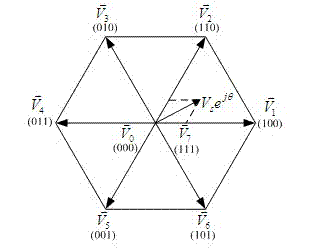
[0115] The basic structure of the three-phase bridge PWM inverter circuit applied in the motor synchronous modulat...


PUM


Abstract

The invention discloses a motor synchronous modulation method and a control system thereof. Under the offline state, the optimization calculation on the switching angle of an inverter is carried out according to the total harmonic loss of the motor; the modulation ratio is taken as an independent variable; m switching angles (Alpha1, Alpha2,..., Alpha m) corresponding to the modulation ratio are worked out by the optimization algorithm; the modulation frequency division number obtained by the m switching angles is 2m+1; the m switching angles are used as a data table memorized in a memory; during the working process, according to the target modulation ratio, the m switching angles can be obtained by searching the data table, thus carrying out conduction control on the inverter switch device. By adopting the method and the technical scheme described by the control method, the running track of the motor magnetic chain can be a regular polygon so as to reduce the output current harmonicsof the inverter, thus improving the control performance of the transmission system.

Description

technical field [0001] The invention relates to a motor control method and its system, in particular to a novel multi-mode synchronous modulation method and its control system applied to an AC drive system. Background technique [0002] The AC drive system refers to a new type of drive system that takes the AC motor as the control object and adjusts the output torque and speed of the motor. Compared with the DC drive system, the AC drive system has good traction performance, high power factor, small size, light weight and reliable operation. The AC drive system is gradually replacing the DC drive system and is widely used in various fields of industrial production, national life and national defense. [0003] The AC transmission system is generally composed of a control system, a main circuit and a control object, among which the main circuit includes a DC bus, a DC support capacitor, and a converter composed of power switching semiconductor devices; the control system is b...

Claims


Application Information

Patent Timeline
Patent Type & Authority Patents(China)
IPC IPC(8): H02P27/06H02P21/14
Inventor 刘可安刘勇尚敬刘良杰
Owner ZHUZHOU CSR TIMES ELECTRIC CO LTD
Why Eureka
Try Eureka