Integrated reinforcement bar pre-binding forming die constructing method for bridge construction

A bridge construction and construction method technology, applied in the direction of manufacturing tools, ceramic molding machines, etc., can solve the problems of difficult to readjust misplaced steel bars, low work efficiency, labor and time-consuming, etc., to achieve improved work efficiency, high work work efficiency, positioning accurate effect

Active Publication Date: 2011-11-02
CHINA RAILWAY 24TH BUREAU GRP +1
View PDF3 Cites 6 Cited by
  • Summary
  • Abstract
  • Description
  • Claims
  • Application Information

AI Technical Summary

Problems solved by technology

[0003] At present, beam-making yards use pre-bundled split steel bars in the binding of steel bars. When the bridge deck pre-tied steel bar cages are hoisted on the bridge body steel bar cages, it is often encountered that the horizontal bar and the vertical wall bar of the web conflict with each other. phenomenon, and it is labor-intensive and time-consuming to adjust, and it is difficult to adjust the misplaced steel bar again;
[0004] Even though some beam-making yards adopt the one-time forming method of integral steel pre-binding, scaffolding is basically used to build fake inner molds when binding bridge deck steel bars on pre-tying tire molds, but the process of dismantling and installing scaffolding is long and the work efficiency is low.

Method used


Image

  • Integrated reinforcement bar pre-binding forming die constructing method for bridge construction
  • Integrated reinforcement bar pre-binding forming die constructing method for bridge construction
  • Integrated reinforcement bar pre-binding forming die constructing method for bridge construction

Examples


Embodiment Construction

[0028] The features of the present invention and other related features will be further described in detail below in conjunction with the accompanying drawings through embodiments, so as to facilitate the understanding of those skilled in the art:

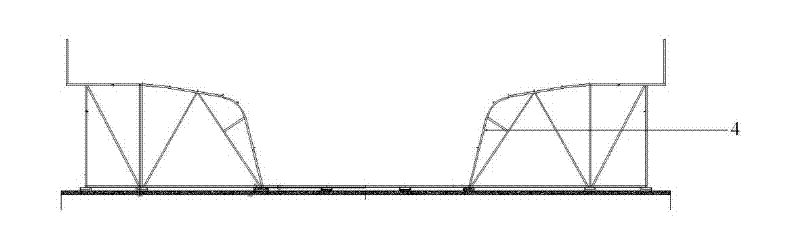
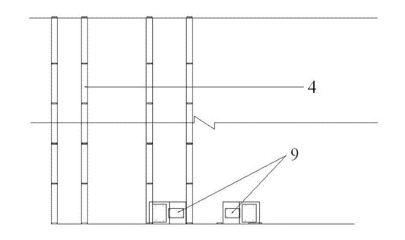
[0029] like Figure 1 to Figure 4 As shown, the general reference signs respectively represent: floor reinforcement cage 1, web reinforcement cage 2, bridge deck reinforcement cage 3, tying mold 4, false intima 5, telescopic support rod 6, weep hole model 7, anti-rail wheel 8. Support plate model 9.

[0030] The design purpose of the present invention is to provide an integral steel bar pre-binding method that facilitates the disassembly and assembly of the inner mold model based on the shortcomings of the existing pre-binding forming methods of steel bars. The general design concept is as follows:

[0031] First, bind the bottom plate reinforcement cage 1 and the web reinforcement cage 2 on a binding mold 4 for controlling the p...


PUM


Abstract

The invention relates to a box beam forming method, in particular to an integrated reinforcement bar pre-binding forming die constructing method for bridge construction. The method is used for carrying out reinforcement bar binding of a box beam outside a beam fabricating station position and is characterized by comprising the following steps of: binding a bottom plate and web reinforcement bars on a binding clamping fixture; longitudinally and sequentially paving a reversal rail wheel and a support frame thereof at the upper edge of the binding clamping fixture; sliding and positioning an artificial inner film into the binding clamping fixture by a wheel shaft; regulating the height of the artificial inner film so that a bridge deck reinforcement cage can be bound on the artificial inner film; and contracting the artificial inner film so that the artificial inner film slides out of the binding clamping fixture. The integrated reinforcement bar pre-binding forming die constructing method for the bridge construction has the advantages that grooving spacer bars are adopted on the pre-binding forming die, fed in one step and accurately positioned, therefore no repeated technical labor of detecting the number of the reinforcement bars and the distance among the reinforcement bars is need in future; the operating work efficiency is high; the production line operation is adopted; and the time spent on the beam fabricating station position is not occupied.

Description

technical field [0001] The invention relates to a forming method of a box girder, in particular to a construction method of an integral reinforced pre-bound tire formwork used for bridge construction. Background technique [0002] In order to improve the binding speed and quality of box girder steel bars, it is undoubtedly the best method to position the steel bars by binding tire molds for box girder steel bars. There is no time for binding steel bars on the beam-making platform. [0003] At present, beam-making yards use pre-bundled split steel bars in the binding of steel bars. When the bridge deck pre-tied steel bar cages are hoisted on the bridge body steel bar cages, it is often encountered that the horizontal bar and the vertical wall bar of the web conflict with each other. phenomenon, and it is labor-intensive and time-consuming to adjust, and it is difficult to adjust the misplaced steel bar again; [0004] Even though some girder yards adopt the one-time forming...

Claims


Application Information

Patent Timeline
Patent Type & Authority Applications(China)
IPC IPC(8): B28B23/14
Inventor 钱明剑徐建宏吴承张
Owner CHINA RAILWAY 24TH BUREAU GRP
Why Eureka
Try Eureka