Discharging device, dust remover and stirring equipment

A technology of unloading device and dust collector, which is applied in the direction of unloading device, mixing plant, removing smoke and dust, etc., can solve the problems of effect discount and dust removal effect of dust collector, and achieve the effect of good applicability and simple and convenient structure.

Active Publication Date: 2013-01-02
SANY HEAVY IND CO LTD (CN)
View PDF3 Cites 0 Cited by
  • Summary
  • Abstract
  • Description
  • Claims
  • Application Information

AI Technical Summary

Problems solved by technology

Since the dust collection pipe 14 and the dust discharge pipe 12 of the dust collector are connected with the stirring main machine cover 13 at the same time, the dust collection pipe 14, the dust discharge pipe 12 and the stirring main machine are connected. When the dust collector 16 collects dust, the dust-containing gas Most of the dust is sucked away by the dust collector through the dust collection pipe, but another part will also enter the dust collector 16 through the dust discharge pipe 12, and at the same time, the dust accumulated on the filter element in the dust collector 16 will also fall to the dust discharge pipe 12. On the other hand, due to the effect of the dust entering the ash discharge pipe from the mixer, the effect of the dust on the filter element falling back into the mixer from the ash discharge pipe is greatly reduced, and finally the dust removal effect of the dust collector is greatly reduced.

Method used


Image

  • Discharging device, dust remover and stirring equipment
  • Discharging device, dust remover and stirring equipment

Examples


Embodiment Construction

[0022] The following will clearly and completely describe the technical solutions in the embodiments of the present invention with reference to the accompanying drawings in the embodiments of the present invention. Obviously, the described embodiments are only some, not all, embodiments of the present invention. Based on the embodiments of the present invention, all other embodiments obtained by persons of ordinary skill in the art without creative efforts fall within the protection scope of the present invention.

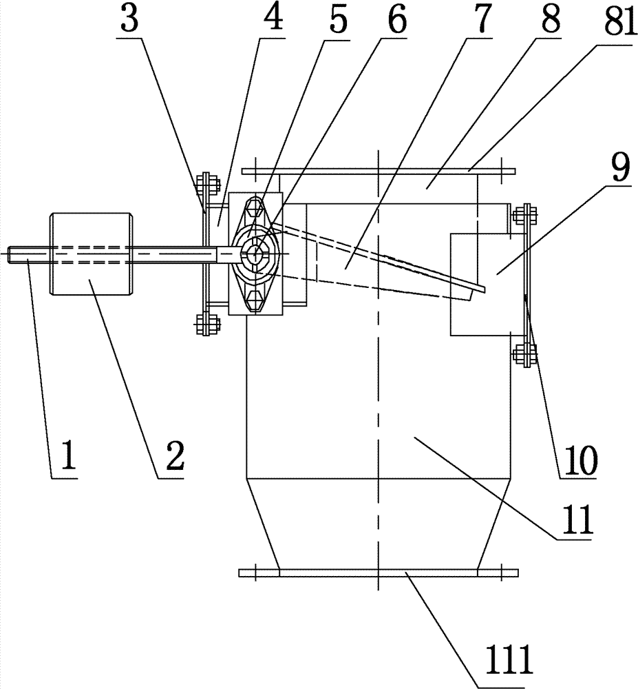
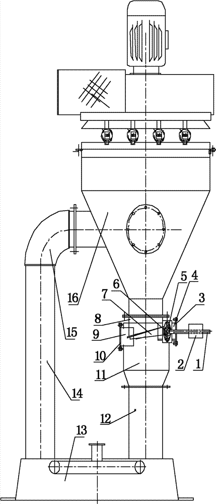
[0023] Such as figure 1 , figure 2 As shown, it is the first embodiment provided by the present invention, a kind of unloading device, including a through unloading cylinder, a rotating shaft 6 arranged on the unloading cylinder, and unloading plates respectively installed on the rotating shaft 6 7 and the reset member, at the initial position where the unloading plate 7 is balanced with the reset member, the unloading plate 7 is closed with the unloading barrel,...


PUM


Abstract

The invention relates to a discharging device, a dust remover and stirring equipment. The discharging device comprises a through discharging cylinder, a rotating shaft, a discharging plate and a resetting piece; at the balanced initial position of the discharging plate and the resetting piece, the discharging plate and the discharging cylinder are closed; and at the imbalance discharging positionof the discharging plate and the resetting piece, the discharging plate and the discharging cylinder are separated. In the dust remover, the discharging device is arranged between a dust collector and a dust discharging pipe. In the discharging device, the volume of a feeding cylinder is reasonably determined according to the dust collecting volume of the dust collector; and adjustment and control of the weight of the dust collected by the dust collector and automatic discharge of the dust can be realized by screwing in or out a counterweight block arranged on a counterweight pull rod and using the lever balance principle. According to the dust remover provided with the discharging device, the discharging plate is opened and closed to play a role in blocking the communication among the dust collecting pipe, the dust collector, the dust discharging pipe and a stirring main machine, so that the dust collector can continuously extract the dust-containing gas in the main machine, and the dust removing efficiency of the main machine is greatly improved.

Description

technical field [0001] The invention relates to a discharge device. In addition, the present invention also relates to a dust remover with the discharge device, and a stirring device with the dust remover. Background technique [0002] With the rapid development of concrete mixing plants (buildings), customers are more and more pursuing product quality, and at the same time pursuing better environmental performance. When the concrete mixing plant is working normally to produce concrete, it is necessary to throw aggregates (sand, stone, water and powder, etc.) Therefore, it is necessary to remove dust from the mixing host. [0003] In the existing mixing station, when the mixing host uses a forced dust collector to remove dust, such as figure 2 Partially shown, generally the dust collector 16 is connected to the top of the stirring main machine cover 13 through the ash collecting pipe 14, and the bottom ash discharge pipe 12 is directly connected to the stirring main machi...

Claims


Application Information

Patent Timeline
Patent Type & Authority Patents(China)
IPC IPC(8): B28C7/16B28C9/02B08B15/04
Inventor 倪小青蒋志辉张架桥
Owner SANY HEAVY IND CO LTD (CN)
Why Eureka
Try Eureka