Headset with earflaps capable of rotating and extending relative to head band
A technology of earmuffs and headbands, which is applied in the direction of earpiece/headphone accessories, etc., can solve the problems of versatility and comfort, easy to get stuck, and affect the service life of mobile phones, etc., and achieve simple and practical structure, long service life and good versatility Effect
- Summary
- Abstract
- Description
- Claims
- Application Information
AI Technical Summary
Problems solved by technology
Method used
Image
Examples
Embodiment 1
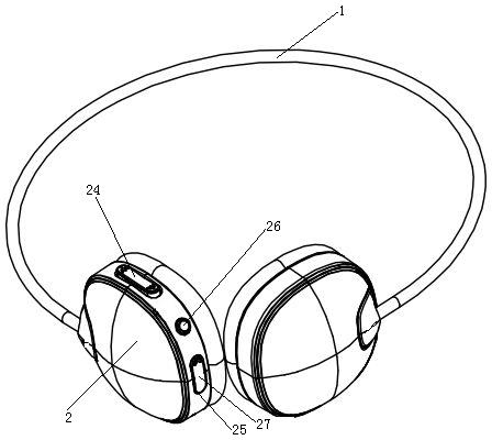
[0031] Embodiment one, seefigure 1 , an earphone with earmuffs that can rotate and stretch relative to the headband, including a headband 1 and a pair of earmuffs 2 arranged at the left and right ends of the headband. The headband 1 is an elastic opening hoop, and the pair of earmuffs 2 pass through The headband 1 is elastically abutted together, and a volume switch 24, a USB interface 25 and a power switch 26 are installed on the surface of the left side of the pair of earmuffs 2, and the upper cover of the USB interface 25 is provided with a USB interface cover 27 , the USB interface cover 27 is movably connected to the earmuffs 2, and the volume switch 24, the USB interface 25 and the power switch 26 are electrically connected to the audio circuit board of the earphone.
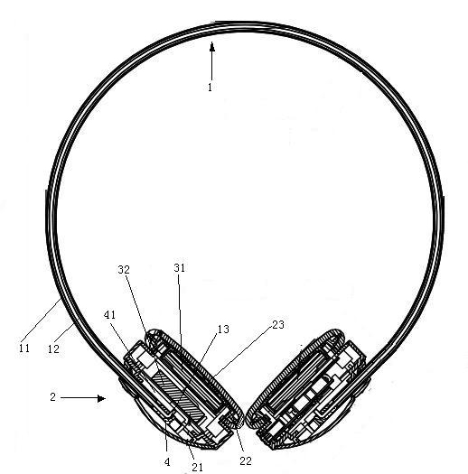
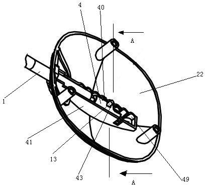
[0032] see figure 2 , the headband 1 includes an inner rod 11 and a sleeve 12 sleeved on the inner rod 11, the inner rod 11 is made of electrophoretic steel wire, the sleeve 12 is a transparent PU tube, a...
Embodiment 2
[0035] Embodiment two, see Figure 5 , the difference from Embodiment 1 is that the end of the inner rod 11 is not provided with an elbow but is provided with an elastic clamping wing 14, and the hole wall of the through hole 42 is provided with a groove 44 that can accommodate the insertion of the clamping wing 14 , the through hole 42 and the groove 44 are enough to form a socket, and the method of inserting the inner rod 11 into the slider 4 is as follows: make the end of the inner rod 11 align with the through hole 42, align the clamping wings 14 with the groove 44, squeeze the inner rod 11 and Slider 4, when the clamping wing 14 reaches the cavity 43, the clamping wing 14 elastically opens, so that the slider 4 cannot be disengaged from the inner rod 11, and the wire 5 is the same as the embodiment from the inner rod 11. The inside passes through and enters the earmuffs 2 to be connected with corresponding components.
[0036] see Image 6 , when the left side 15 of the...
Embodiment 3
[0038] Embodiment three, see Figure 10 , the difference with the second embodiment is that the elastic fastener 40 and the corrugated groove 49 are not provided, the gap fit between the slider 4 and the chute 41, the slider 4 is made of plastic, and the surface of the slider is plated with The steel adsorption layer 47 is inlaid with a permanent magnet 46 in the chute 41, and utilizes the attraction force of the permanent magnet 46 to the adsorption layer 47 to realize the fixing of the slider 4 and the chute 5, so that the earmuffs are hung on the headband.
PUM
 Abstract
Description
Claims
Application Information
 - R&D
- Intellectual Property
- Life Sciences
- Materials
- Tech Scout
- Unparalleled Data Quality
- Higher Quality Content
- 60% Fewer Hallucinations
Browse by: Latest US Patents, China's latest patents, Technical Efficacy Thesaurus, Application Domain, Technology Topic, Popular Technical Reports.
© 2025 PatSnap. All rights reserved.Legal|Privacy policy|Modern Slavery Act Transparency Statement|Sitemap|About US| Contact US: help@patsnap.com


