Necking detection and control method of melting electrode and electric arc welding

A melting electrode and arc welding technology, which is applied to arc welding equipment, welding equipment, manufacturing tools, etc., can solve the problems of small suppression effect and unstable welding state, so as to improve the suppression effect, stabilize the welding state and improve the sensitivity Effect

Active Publication Date: 2014-12-31
DAIHEN CORP
View PDF10 Cites 0 Cited by
  • Summary
  • Abstract
  • Description
  • Claims
  • Application Information

AI Technical Summary

Problems solved by technology

As a result, the effect of suppressing the amount of sputtering is reduced, and the welding state may become unstable due to the constriction detection control.

Method used


Image

  • Necking detection and control method of melting electrode and electric arc welding
  • Necking detection and control method of melting electrode and electric arc welding
  • Necking detection and control method of melting electrode and electric arc welding

Examples


Embodiment approach 1

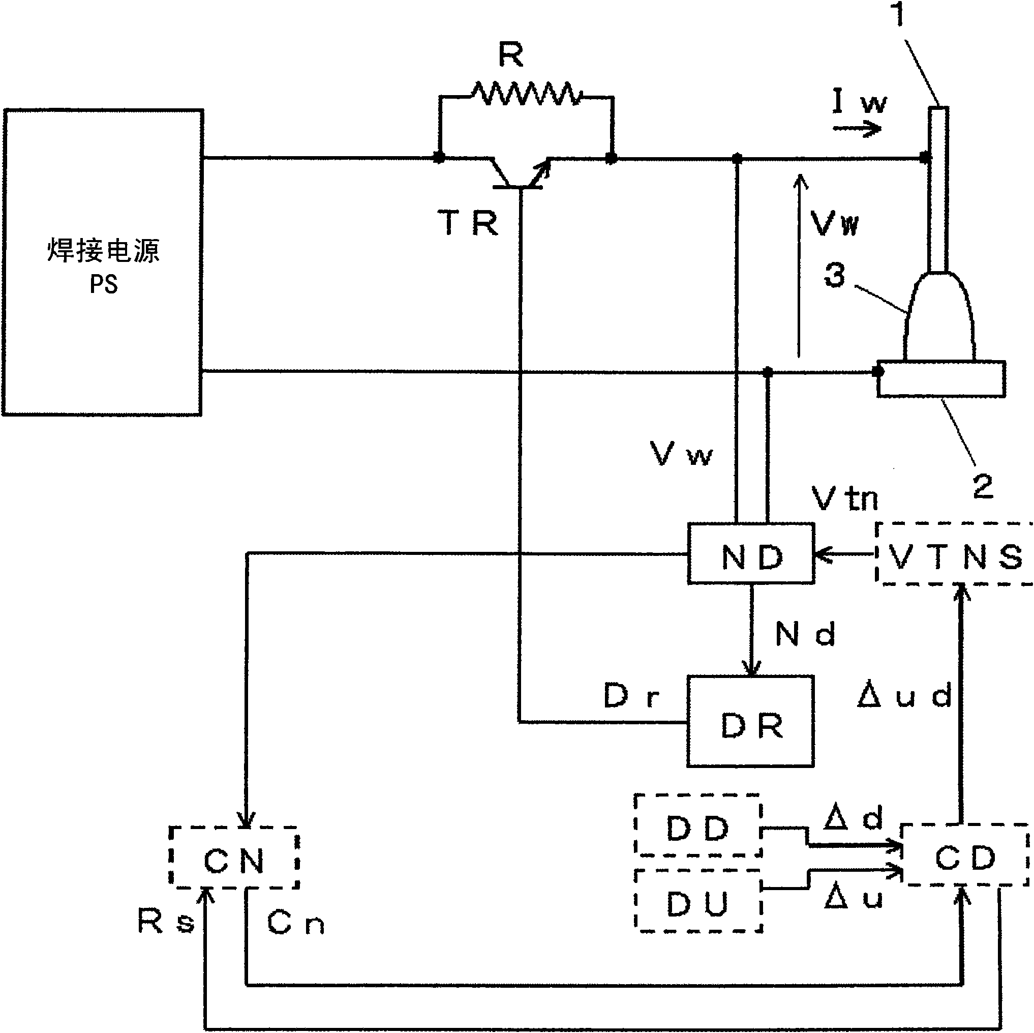
[0079] In the constriction detection control method according to Embodiment 1 of the present invention, the constriction detection time Tn is detected for each short circuit, and when the constriction detection time Tn is less than or equal to the lower limit time Lt, 1 is subtracted from the count value Cn, and when When the upper limit time Ht is above, add 1 to the count value Cn, when the count value reaches the negative reference value Lc, reduce the necking detection reference value Vtn by the decrease value Δd, and reset the count value Cn to 0, when the count value Cn When the positive reference value Hc is reached, the constriction detection reference value Vtn is increased by the increment value Δu, and the counter value Cn is reset to 0, and the correction of the constriction detection reference value Vtn is continued during welding. Hereinafter, Embodiment 1 will be described.

[0080] figure 1 It is a block diagram of a welding device for carrying out the constr...

Embodiment approach 2

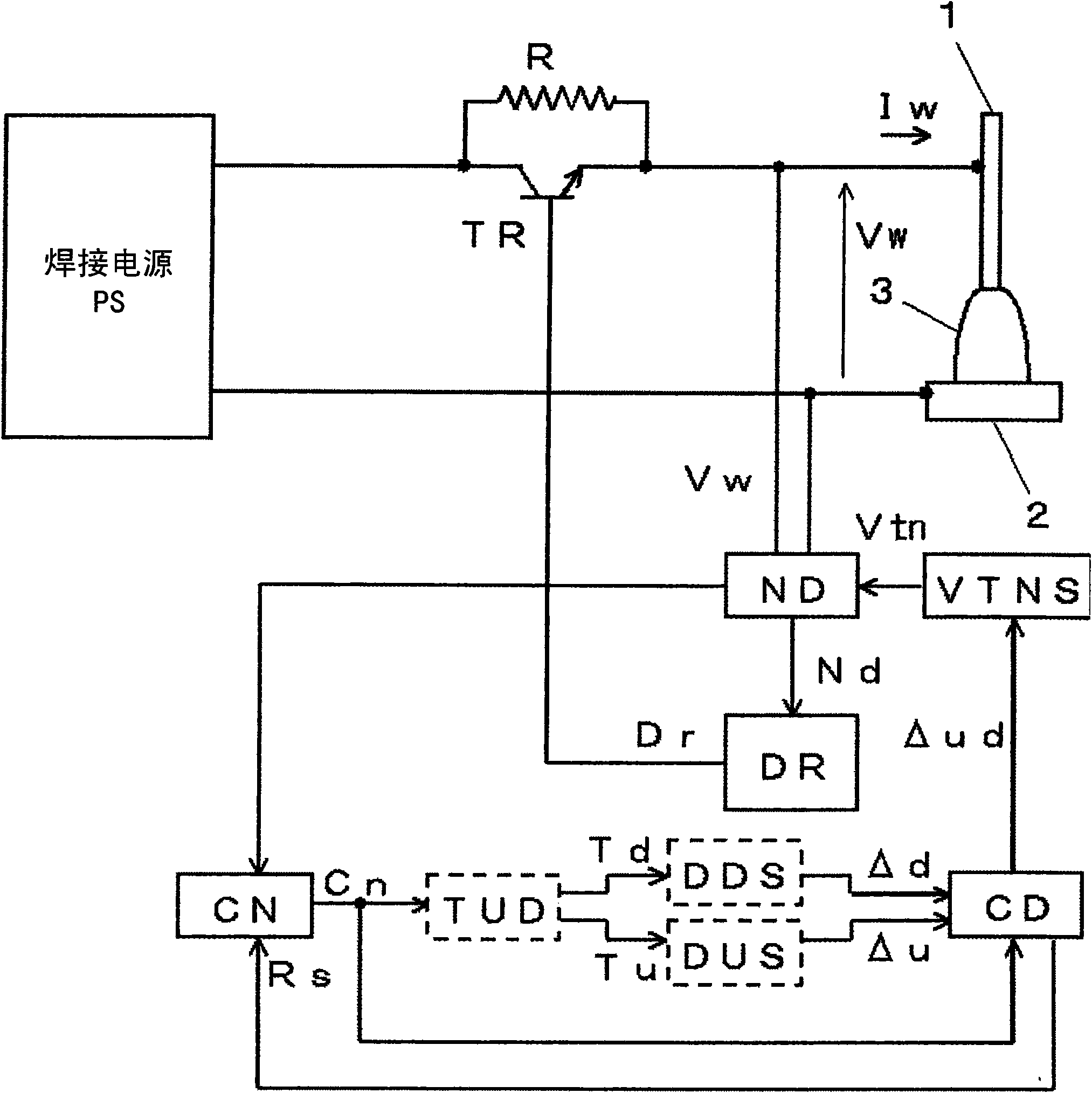
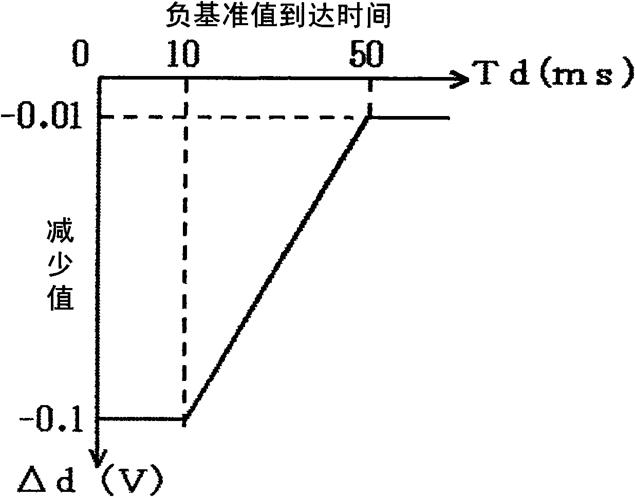
[0093] In the constriction detection control method according to Embodiment 2 of the present invention, the above-mentioned decrement value Δd is associated with the negative reference value arrival time Td from the time when the count value Cn is reset to 0 until the negative reference value Lc is reached. The above-mentioned increase value Δu is changed correspondingly to the positive reference value arrival time Tu from the time when the above-mentioned counter value Cn is reset to 0 until reaching the above-mentioned positive reference value Hc. Hereinafter, Embodiment 2 will be described.

[0094] figure 2 It is a block diagram of a welding apparatus for carrying out the constriction detection control method of the molten electrode arc welding according to the second embodiment. This figure is similar to the above Figure 5 as well as figure 1 Correspondingly, the same symbols are assigned to the same modules, and their descriptions are omitted. The graph is in fi...


PUM


Abstract

The invention provides a necking detection and control method of melting electrode and electric arc welding in order to improve the detection precision of the necking during the melting of electrode and electric arc. The necking of droplets can be detected in a manner that the change of a resistance value between a melting electrode (1) and a base material (2) reaches to a necking detection reference value (Vtn). If necking is detected, the welding current is reduced, and output control can be conducted under the state of low current value, regenerating electric arc. The necking detection time is calculated from the detection time of the necking phenomenon to the regeneration of electric arc based on each short circuit. When the necking detection time is below a lower limit time, one is subtracted from a count value. When the necking detection time is above an upper limit time, one is added to the count value. When the count value reaches to a negative reference value, the necking detection reference value (Vtn) is reduced. When the count value reaches to a positive reference value, the necking detection reference value (Vtn) is increased. Accordingly, as the necking detection reference value (Vtn) can be appropriate, the detection precision of the necking can be improved.

Description

technical field [0001] The invention relates to a necking detection and control method for melting electrode arc welding, which is used for detecting the necking phenomenon of molten droplets during a short circuit and reducing the welding current so as to improve the welding quality. Background technique [0002] Figure 4 It is a diagram showing current-voltage waveforms and droplet transfer in metal arc welding in which the short-circuit period Ts and the arc period Ta are repeated. The figure (A) shows the time change of the welding current Iw that energizes the molten electrode (hereinafter referred to as welding wire 1), and the figure (B) shows the time change of the welding voltage Vw applied between the welding wire 1 and the base metal 2. , Figures (C) to (E) show the transition of the droplet 1a. Hereinafter, description will be made with reference to this figure. [0003] During the short-circuit period Ts from time t1 to t3, the droplet 1a at the tip of the we...

Claims


Application Information

Patent Timeline
Patent Type & Authority Patents(China)
IPC IPC(8): B23K9/095
Inventor 井手章博
Owner DAIHEN CORP
Why Eureka
Try Eureka