Conveyer belt capable of being matched with fishbone-shaped groove encapsulation roller for use

A technology of rubber-coated rollers and conveyor belts, applied in the field of conveyor belts and rollers, can solve the problem that the fishbone-shaped groove rubber-coated rollers cannot be used together, and achieves small extrusion deformation, improved tear resistance, and no reduction in friction coefficient. Effect

Inactive Publication Date: 2011-11-09
SHANGHAI KEDA HEAVY IND GROUP
View PDF6 Cites 2 Cited by
  • Summary
  • Abstract
  • Description
  • Claims
  • Application Information

AI Technical Summary

Problems solved by technology

[0005] The object of the present invention is to provide a conveyor belt used in conjunction with herringbone-shaped groove rubberized rollers to solve the problem in the prior art that the conveyor belt cannot be used in conjunction with the improved herringbone-shaped grooved rubberized rollers

Method used


Image

  • Conveyer belt capable of being matched with fishbone-shaped groove encapsulation roller for use
  • Conveyer belt capable of being matched with fishbone-shaped groove encapsulation roller for use
  • Conveyer belt capable of being matched with fishbone-shaped groove encapsulation roller for use

Examples


Embodiment 1

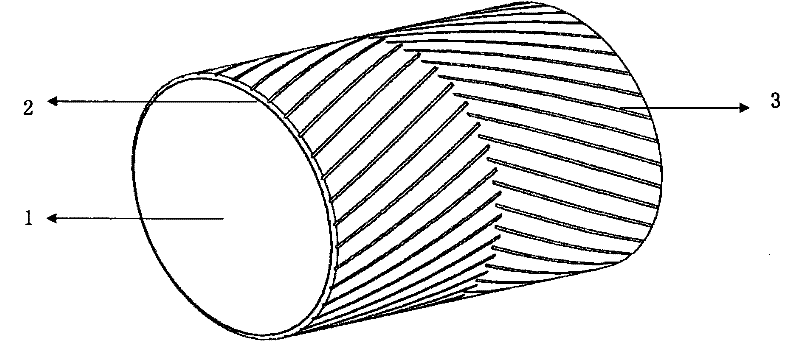
[0016] Such as figure 1 As shown, the rubber-coated roller used in this embodiment includes a drum body 1, the drum body is made of metal, and a layer of integral rubber-coated 2 is wrapped on the outer circumferential surface of the metal drum, and the rubber-coated surface The left and right sides are provided with strip grooves 3, and the grooves on the left and right sides are staggered at the center line of the drum body.

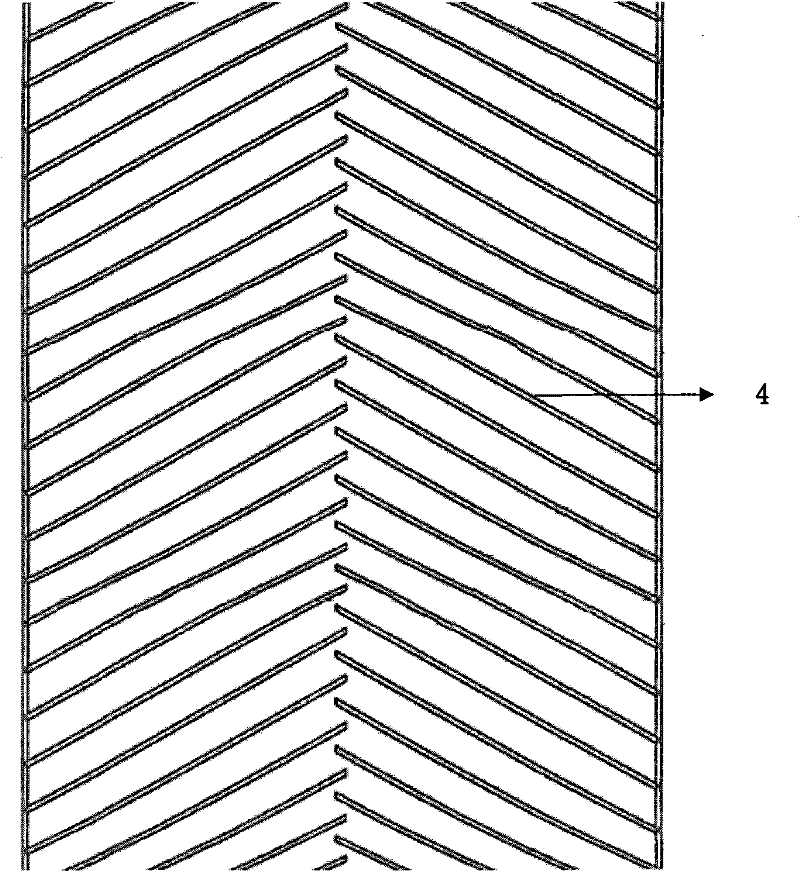
[0017] Such as figure 2 As shown, for the above-mentioned herringbone-shaped groove rubber-coated roller, the conveyor belt of this embodiment is improved and designed accordingly. The strip-shaped protrusions 4 that match the glue grooves, the protrusions 4 on the lower surface of the conveyor belt body are distributed in a fishbone shape, and the herringbone shape distribution means that the protrusions on both sides of the lower surface of the conveyor belt body are staggered at the center line of the conveyor belt .

[0018] When using the rubb...

Embodiment 2

[0020] The rubber-covered roller used in this embodiment is the same as that in Embodiment 1.

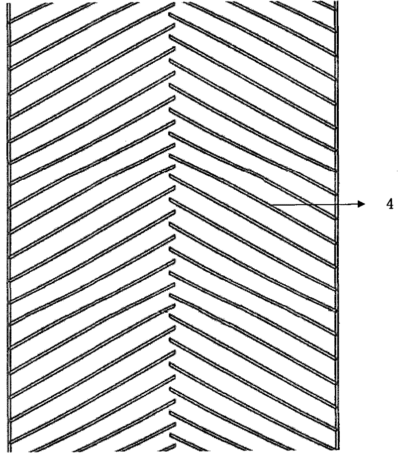
[0021] Such as figure 2 As shown, the conveyor belt in this embodiment includes a conveyor belt body, the lower surface of the conveyor belt body is provided with a strip-shaped protrusion 4 that matches the rubber groove on the circumferential surface of the drum body, and the lower surface of the conveyor belt body The protrusions 4 are distributed in a herringbone shape, which means that the protrusions on both sides of the lower surface of the conveyor belt body are staggered at the center line of the conveyor belt. The heights of the protrusions are the same. The protrusions have the same length. The protrusion is permanently fixed on the belt body of the conveyor belt by an integral rubber plate through an adhesive or a thermal vulcanization process.

[0022] When using the rubberized roller of this embodiment, since the strip grooves on the left and right sides of the rol...


PUM


Abstract

The invention relates to a conveyer belt capable of being matched with a fishbone groove encapsulation roller for use. The conveyer belt comprises a conveyer belt body. The conveyer belt is characterized in that strip protuberances matched with encapsulation grooves on the circumferential surface of a roller body are arranged on the lower surface of the conveyer belt body and the protuberances on the lower surface of the conveyer belt body are distributed in a fishbone shape. The strip grooves at the left side and right side of the surface of a roller are not intersected, thus the extrusion deformation of the encapsulation is small and the tearing resistance is improved compared with those of a herringbone groove rubber surface; water and dirt on the surface of the encapsulation roller can be discharged into the strip grooves from the surface of the conveyer belt by virtue of extrusion when the conveyer belt is contacted with the surface of the roller, thus the encapsulation roller can be used in a damp environment and even a worse environment, and the encapsulation roller is ensured to be completely laminated with an adhesive tape while the friction coefficient is not reduced.

Description

technical field [0001] The invention relates to a roller in the field of conveying machinery, in particular to a conveyor belt used in conjunction with a herringbone groove rubber-covered roller. Background technique [0002] The rubber-covered pulley is an important part and part of the belt conveyor system. The rubber-covered pulley can effectively improve the operation of the conveying system, protect the metal pulley from wear, prevent the conveyor belt from slipping, and make the pulley and the belt run synchronously, thus ensuring The belt runs efficiently and with a large capacity; the rubber lagging of the pulley can also effectively prevent the sliding friction between the pulley and the belt, reduce the material adhesion on the surface of the pulley, and thus reduce the deviation and wear of the belt. [0003] Rubber conveyor belts are widely used for their smooth transmission, easy installation and maintenance, and low cost of use. And the defect that exists is t...

Claims


Application Information

Patent Timeline
Patent Type & Authority Applications(China)
IPC IPC(8): B65G15/42
Inventor 廖微微
Owner SHANGHAI KEDA HEAVY IND GROUP
Why Eureka
Try Eureka