
Ohmic heating method and ohmic heating device

A heating method and power supply technology, applied in heat treatment furnaces, heat treatment equipment, furnaces, etc., can solve the problems of inability to quench the tooth surface, difficult to guarantee the quality of quenching or annealing, and low operating efficiency, and achieve the effect of high-efficiency quenching or annealing.

Active Publication Date: 2011-11-09
宫电高周波设备(上海)有限公司
View PDF5 Cites 5 Cited by
  • Summary
  • Abstract
  • Description
  • Claims
  • Application Information

AI Technical Summary

Problems solved by technology

[0003] However, this energized heating device makes a pair of contacts contact the tooth surface or the back of the rack, and then supplies the specified output current to the tooth surface or the back respectively, so as to achieve the purpose of heating the tooth surface or the back of the rack for quenching. However, after the back of the rack is quenched, it cannot continue to quench the tooth surface
Therefore, the quenching or tempering of the back of the rack and the tooth surface cannot be performed in a substantially continuous operation cycle, and there are problems such as low working efficiency and difficulty in guaranteeing the quality of quenching or annealing of the back of the rack or the tooth surface.

Method used


Image

  • Ohmic heating method and ohmic heating device
  • Ohmic heating method and ohmic heating device
  • Ohmic heating method and ohmic heating device

Examples


Embodiment Construction

[0025] The best mode adopted for carrying out the present invention will be described in detail below based on the drawings.

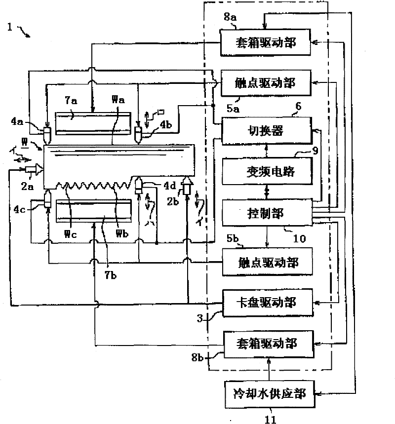
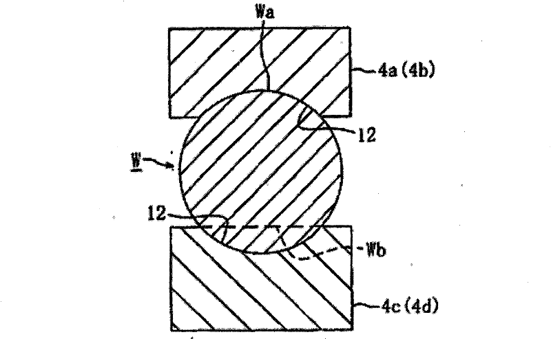
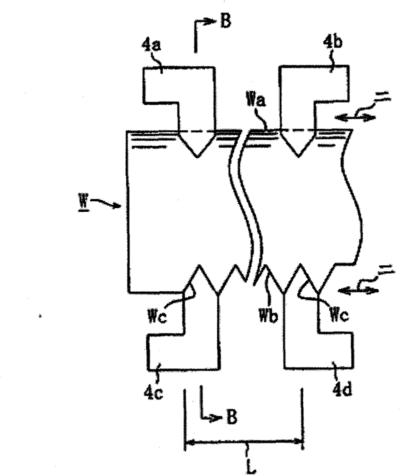
[0026] Figure 1 ~ Figure 7 This shows an embodiment when the energization heating device according to the present invention is used for rack quenching. Such as figure 1 As shown, the rack (hereinafter referred to as the workpiece W) to which the energization heating device 1 of the present invention is applied is composed of a tooth surface Wb having a relative axis of helical teeth at a predetermined angle, and a semicircular arc on the opposite side of the tooth surface Wb The backside Wa structure of the surface composition.

[0027] Then, the energized heating device 1 is equipped with the following devices: left and right chucks 2a, 2b supporting both ends of the workpiece W as supporting means, and the chucks 2a, 2b are moved in the direction indicated by the arrow ii and clamped or loosened The chuck drive unit 3 composed of the click of the workp...


PUM


Abstract

The invention relates to an ohmic heating method and an ohmic heating device. Through the ohmic heating method and the ohmic heating device, the quenching or annealing of the back surface and tooth surface of a workpiece can be carried out in a roughly continuous operation period, and the high-precise quenching or annealing quality is easily obtained on the back surface or tooth surface while striving to improve the efficiencies of quenching or annealing. The ohmic heating method is characterized by comprising the following steps that a switching device is switched to a back surface side, so that one pair of first touch points contact the two ends of the heating range in the length direction of the back surface of the workpiece supported by a support device, the regulated frequency and output current for the back surface are supplied to the touch points from a power supply device, and then ohmic heating is carried out on the back surface; and after the step, the switching device is switched to a tooth surface side, so that one pair of second touch points contact the two ends of the heating range in the length direction of the tooth surface of the workpiece, the regulated frequency and output current for the tooth surface are supplied to the touch points from the power supply device, and then the ohmic heating is carried out on the tooth surface.

Description

Technical field [0001] The invention relates to an energized heating method and an energized heating device used when quenching or tempering the back surface and tooth surface of a workpiece such as a steering rack and the like by energizing heating. Background technique [0002] Originally, as this type of energized heating device, for example, it is disclosed in Patent Document 1 (e.g., Japanese Patent No. 4232973). This kind of energized heating device is equipped with a pair of energized electrodes (contacts) arranged facing each other within the heating range along the length direction of the rack, a power supply device that supplies the energized electrodes with a current of a predetermined frequency, and is offset from the opposite direction of the energized electrodes The position starts to extend in the horizontal direction that intersects the opposing direction substantially in a straight line, through which a predetermined current is supplied from the energizing electr...

Claims


Application Information

Patent Timeline
Patent Type & Authority Applications(China)
IPC IPC(8): C21D9/32C21D1/18C21D1/34
Inventor 宫崎力
Owner 宫电高周波设备(上海)有限公司
Learn More