Input device and input method based on multi-finger capacitive touch technology
A multi-finger touch and input device technology, applied in the field of mobile phones, e-books or other artificial intelligence systems, handheld computers, computers, can solve the problems of easy to get dirty, hard to clean, leave fingerprints, oil stains, inconvenient operation, etc., to achieve the goal of using Convenience, easy cleaning, long-lasting effect
- Summary
- Abstract
- Description
- Claims
- Application Information
AI Technical Summary
Problems solved by technology
Method used
Image
Examples
Embodiment 1
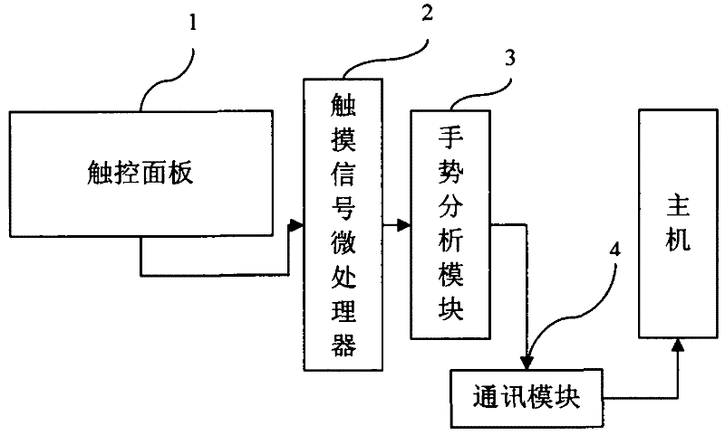
[0053] like figure 1 A human-machine input device based on multi-finger touch technology is shown, including a touch panel 1 , a touch signal microprocessor 2 , a gesture analysis module 3 and a communication module 4 .
[0054] The working method of the above-mentioned man-machine input device based on the multi-finger capacitive touch technology is as follows: the touch signal microprocessor 2 judges the corresponding position of the finger on the touch sensor panel through detection, and outputs to the gesture analysis module 3 through coding, including the touch hand. Index, corresponding touch coordinates and touch pressure and other information; Gesture analysis module 3 judges various touch gestures including each finger coordinate, moving direction and speed, finger click or double click, drag after clicking, and click virtual according to the aforementioned signals. Keys such as keyboard keys and multiple virtual keyboard combinations send information to the communica...
Embodiment 2
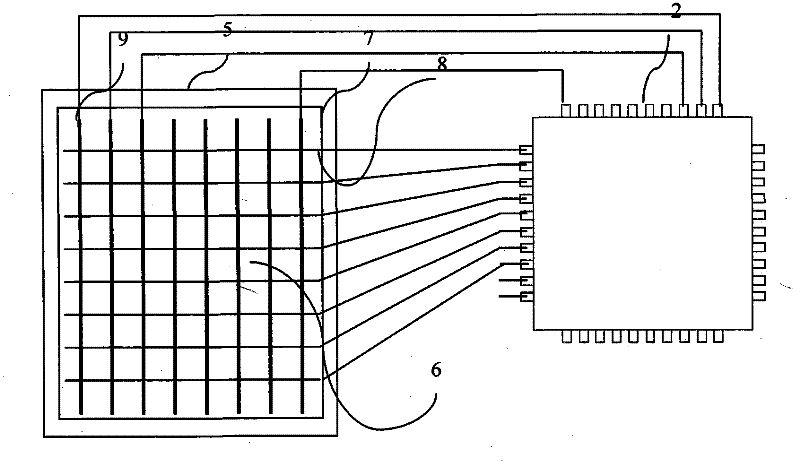
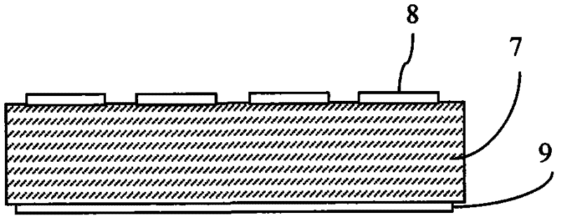
[0056] The structure of the touch panel 1 described in Implementation 1 is as follows: figure 2 , Figures 3a-3c As shown, it is composed of a protective panel 5 and a capacitive touch sensor 6. The capacitive touch sensor 6 includes an insulating plate 7 and a row scanning electrode 8 and a column scanning electrode 9 made on the insulating plate 7, and the row scanning electrode 8 and the column scanning electrode 9 is connected with the touch signal microprocessor 2, wherein the sensing area in the row scanning electrode 8 and the column scanning electrode 9 can be rhombus, as Figure 4 As shown, it can also be a straight line or a curved line; wherein the row scanning electrodes 8 and the column scanning electrodes 9 can be made on both sides of the insulating plate 7 respectively, or can be made on the same side of the insulating plate 7, and the intersection is through the conductive via hole 7a Connect or surface make insulating layer 7b by conducting bridge 7c and co...
Embodiment 3
[0059] like Image 6 As shown, the touch panel 1 in Embodiments 1 and 2 can be divided into an input area 1a and a functional area 1b; wherein the functional area 1b is located at the front end or both sides of the touch panel 1, and one or more keys or virtual keys 10 can be set , the virtual key can utilize the touch scanning area contained in the row and column scanning electrodes, and can also make independent sensing electrodes directly connected to the touch signal microprocessor 2 for special function keys such as power switch and volume adjustment and to control the touch response of the input area 1a. Switch between keyboard input, touch input, and other extended functions. When the finger selects the keyboard input in the functional area 1b, the gesture analysis module 3 finds the corresponding key value in the coordinate lookup table at the position of the finger in the control input area 1a; Key actions such as tapping and long pressing or key combination; at the ...
PUM
| Property | Measurement | Unit |
|---|---|---|
| Thickness | aaaaa | aaaaa |
Abstract
Description
Claims
Application Information
 - R&D
- Intellectual Property
- Life Sciences
- Materials
- Tech Scout
- Unparalleled Data Quality
- Higher Quality Content
- 60% Fewer Hallucinations
Browse by: Latest US Patents, China's latest patents, Technical Efficacy Thesaurus, Application Domain, Technology Topic, Popular Technical Reports.
© 2025 PatSnap. All rights reserved.Legal|Privacy policy|Modern Slavery Act Transparency Statement|Sitemap|About US| Contact US: help@patsnap.com


