Method for automatically forming patterns in design of power system of thermal power plant

A technology for power supply systems and thermal power plants, applied in computing, electrical digital data processing, special data processing applications, etc., can solve problems such as rework, poor practicability, and large limitations of finished templates

Active Publication Date: 2011-11-09
内蒙古电力勘测设计院有限责任公司
View PDF1 Cites 16 Cited by
  • Summary
  • Abstract
  • Description
  • Claims
  • Application Information

AI Technical Summary

Problems solved by technology

[0011] In the traditional power system design method, the recording of electrical equipment information must be careful, a little negligence will affect all subsequent work, and rework may occur; in the screening process of electrical equipment, once the screening is wrong, the subsequent There will be a wide range of changes in the work; power system configuration diagrams, terminal block design, and electrical equipment table production will repeatedly fill in the equipment number and name, all of which are manually entered, and require one-to-one correspondence. requirements, but it also brings a lot of tedious and repetitive workload to the design work, and the error rate and finished product quality cannot be guaranteed
[0012] At present, in the design of the power system, there is still a way to associate the blocks in the CAD drawing elements with the database platform, store all the data in the database, and write the data into the template by pre-customizing the template, this method cannot be separated from the database It runs independently, and the finished product template is too limited, and the finished product drawn requires a lot of manual modification, which is not very practical

Method used


Image

  • Method for automatically forming patterns in design of power system of thermal power plant
  • Method for automatically forming patterns in design of power system of thermal power plant
  • Method for automatically forming patterns in design of power system of thermal power plant

Examples


Embodiment Construction

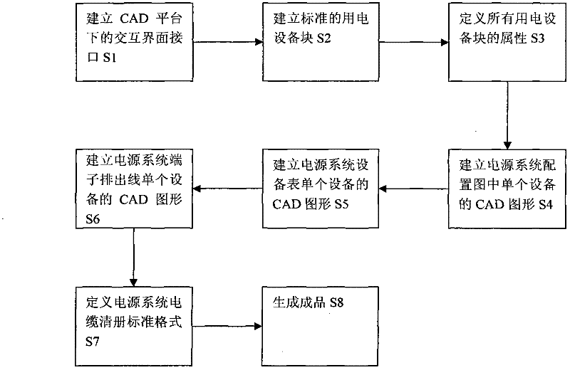
[0026] figure 1 Show the main flow of the method that the present invention proposes, as figure 1 As shown, the method proposed by the present invention includes: step S1, establishing an interactive interface interface under the CAD platform; step S2, establishing a standard electrical equipment block; step S3, defining the attributes of all electrical equipment blocks; step S4, establishing a power supply The CAD drawing of a single device in the system configuration diagram; step S5, establish the CAD drawing of a single device in the power system equipment table; step S6, establish the CAD drawing of a single device of the power system terminal discharge line; step S7, define the standard format of the power system cable list; In step S8, a finished product is generated.

[0027] The following is a detailed introduction to the above 8 steps:

[0028] Step S1, establishing an interactive interface interface under the CAD platform.

[0029] CAD allows users to customize m...


PUM


Abstract

The invention discloses a method for automatically forming patterns in the design of a power system of a thermal power plant, and belongs to the technical field of thermal power plant engineering design department power system design. The method comprises the following steps of: 1, establishing an interaction interface under a computer aided design (CAD) platform; 2, establishing standard electric equipment blocks; 3, defining the attributes of all the electric equipment blocks; 4, establishing CAD patterns of single devices in a power system deployment diagram; 5, establishing the CAD patterns of the single devices of a power system device list; 6, establishing the CAD patterns of the single devices of a power system terminal board outgoing line; 7, defining the standard format of a power system cable inventory; and 8, generating a finished product. By the method, the technical problems of power supply device missing, writing errors, finished product format non-uniformity and the like in the conventional power system design methods are solved.

Description

technical field [0001] The invention belongs to the field of power supply system design of a thermal power plant engineering design unit, and specifically relates to a method for automatically forming drawings for the design of a thermal power plant power supply system. Background technique [0002] AutoCAD is computer-aided design, which is a computer software that uses computers and graphics equipment to help designers carry out design work, referred to as CAD. [0003] Thermal power plant thermal control professional power system design is mainly divided into 380VAC and 220VAC power system. Among them, the design of 380VAC power supply system is divided into two design methods: intelligent integrated electric device and non-integrated electric device; while 220VAC power supply system includes electric equipment with power distribution only and electric equipment with control loop; The electrical equipment of the circuit is also divided into single electric control and do...

Claims


Application Information

Patent Timeline
Patent Type & Authority Applications(China)
IPC IPC(8): G06F17/50
Inventor 吕科王强韩洛奇姜世平杨大为
Owner 内蒙古电力勘测设计院有限责任公司
Why Eureka
Try Eureka