Eureka AIR delivers breakthrough ideas for toughest innovation challenges, trusted by R&D personnel around the world.

Filtering structure of magnetron

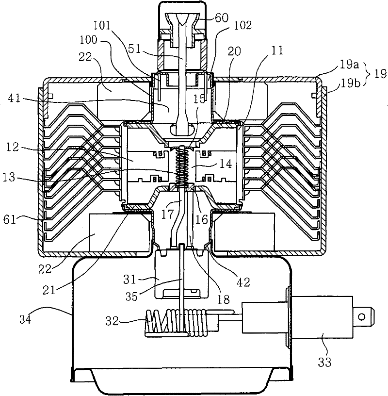
A filter structure and magnetron technology, applied in the field of magnetron, can solve problems such as equipment electromagnetic interference, harmonic leakage, magnetron ignition, etc., achieve good shielding effect, reduce electromagnetic interference, and reduce damage.

Inactive Publication Date: 2011-11-09
LG ELECTRONICS (TIANJIN) APPLIANCES CO LTD
View PDF0 Cites 6 Cited by
  • Summary
  • Abstract
  • Description
  • Claims
  • Application Information

AI Technical Summary

Problems solved by technology

[0014] When the magnetron starts to work, high-frequency harmonics are generated in the magnetron, and usually the high-frequency harmonics can be better suppressed in the antenna cover on the upper part of the magnetron, but in the downward direction of the magnetron , part of the energy, that is, high-frequency harmonics, radiates outward through the cathode lead-out wire under the negative electrode of the magnetron. This part of energy is likely to cause ignition outside the magnetron, and it is easy to cause electromagnetic interference to the equipment around the microwave oven, affecting It will affect the working efficiency of the magnetron itself, and even endanger the health of the operator. The higher the power of the magnetron, the more obvious the harmonic leakage.

Method used


Image

  • Filtering structure of magnetron
  • Filtering structure of magnetron
  • Filtering structure of magnetron

Examples


Embodiment Construction

[0034] The present invention will be described in detail below in conjunction with the accompanying drawings and embodiments.

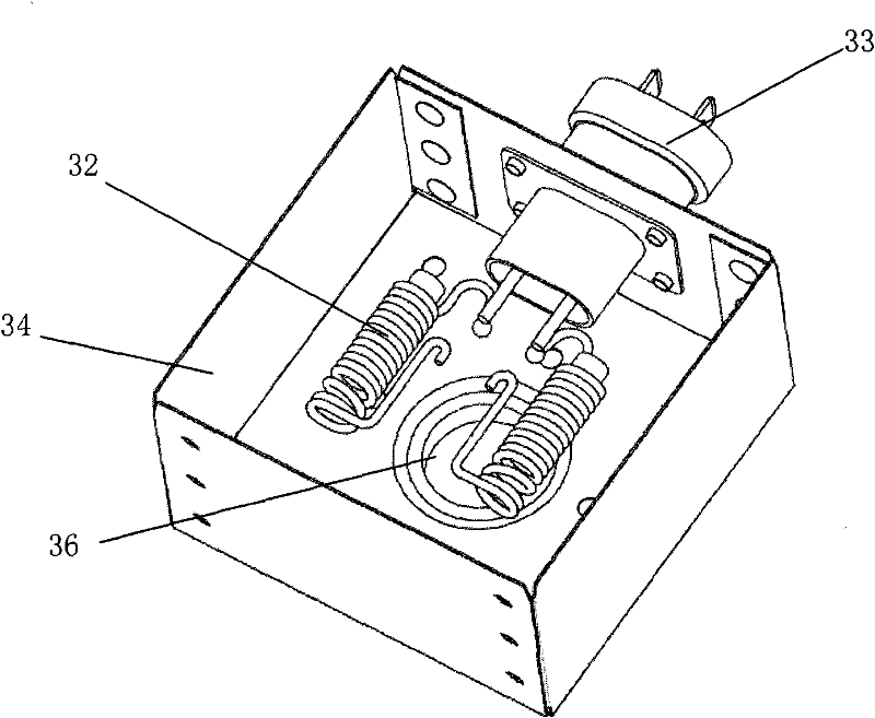
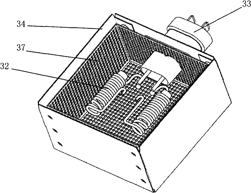
[0035] image 3 is the internal schematic diagram of the filtering structure of the magnetron of the present invention; Figure 4 It is an internal sectional view of the filter structure of the magnetron of the present invention.

[0036] Such as image 3 , Figure 4 As shown, a ceramic part is arranged at the position of the lower sealed chamber corresponding to the lower magnetic pole at the lower end of the magnetron, and the ceramic part is closely combined with the lower cover forming the lower sealed chamber; two cathode lead wires passing through the ceramic part are arranged in the ceramic part In addition, a filter coil 32 with filter function is set, and two sections of filter coils are respectively connected to one end of the central guide rod of the filament and one end of the side guide rod through the cathode lead-out wire; a shieldin...


PUM


Abstract

The invention discloses a filtering structure of a magnetron. The structure is arranged on the lower part of the magnetron and comprises a filtering coil, a central guide rod, a side guide rod, a shielding box and a capacitor, wherein the central guide rod and the side guide rod are connected with filaments in the magnetron respectively; the shielding box encircles the filtering coil; a closed space is formed inside the shielding box; the lower end of a ceramic part of the magnetron passes through a through hole in the upper part of the shielding box and is fixed with the shielding box; the capacitor is arranged outside the shielding box and connected with the filtering coil; and a shielding layer which encircles the filtering coil is arranged in the space inside the shielding box. Microwaves which are guided from a cathode outgoing line can be diffused into a space which is formed by the shielding layer, and electromagnetic waves can be prevented from passing through mesh holes, which are less than one fourth of the wavelength of the microwaves, in the shielding layer, so the leaked microwaves have a loss in the shielding layer, high-frequency harmonic waves are avoided from being diffused from the cathode outgoing line to the outside, and a harmonic noise and a linearly-conducted noise which are generated during the operation of the magnetron can be well shielded.

Description

technical field [0001] The invention belongs to the technical field of magnetrons, and in particular relates to a shielding layer with a mesh structure arranged inside the shielding box, which prevents electromagnetic waves from passing through the meshes, thereby effectively reducing the leakage of high-frequency harmonics and reducing the The filter structure of the magnetron for external radiation. Background technique [0002] figure 1 It is a longitudinal sectional view of a magnetron structure in the prior art; figure 2 is the internal schematic diagram of the filter structure of the magnetron in the prior art. [0003] Such as figure 1 , figure 2 As shown, the magnetron mainly includes: a positive electrode part; a negative electrode part; a magnetic pole part; and a microwave emitting part. The positive electrode part is composed of a barrel-shaped positive electrode case 11, and a plurality of radial blades 12 are formed on the inner wall of the positive elec...

Claims


Application Information

Patent Timeline
IPC IPC(8): H01J23/15H01J23/54H01J25/50
Inventor 王媛
Owner LG ELECTRONICS (TIANJIN) APPLIANCES CO LTD
Why Eureka
Eureka Blog
Learn More