Electric connector for circuit substrate

A technology for circuit substrates and electrical connectors, applied in circuits, connections, fixed connections, etc., can solve the problems of weakened resilience and connector locking function, and achieve the effect of avoiding large-scale and difficult reduction of resilience

Active Publication Date: 2011-11-09
HIROSE ELECTRIC GROUP
View PDF8 Cites 9 Cited by
  • Summary
  • Abstract
  • Description
  • Claims
  • Application Information

AI Technical Summary

Problems solved by technology

Therefore, for this upper arm part, the elastic displacement is repeated due to a large force, and the so-called "slack (ヘたり)" phenomenon in which the restoring force is weakened is likely to occur.
As a result of this "loosening", the elastically displaced upper arm portion does not return to the position where it can engage with the hook portion when the connector is mated, and the locking function of the connector may be reduced.

Method used


Image

  • Electric connector for circuit substrate
  • Electric connector for circuit substrate
  • Electric connector for circuit substrate

Examples


no. 1 approach

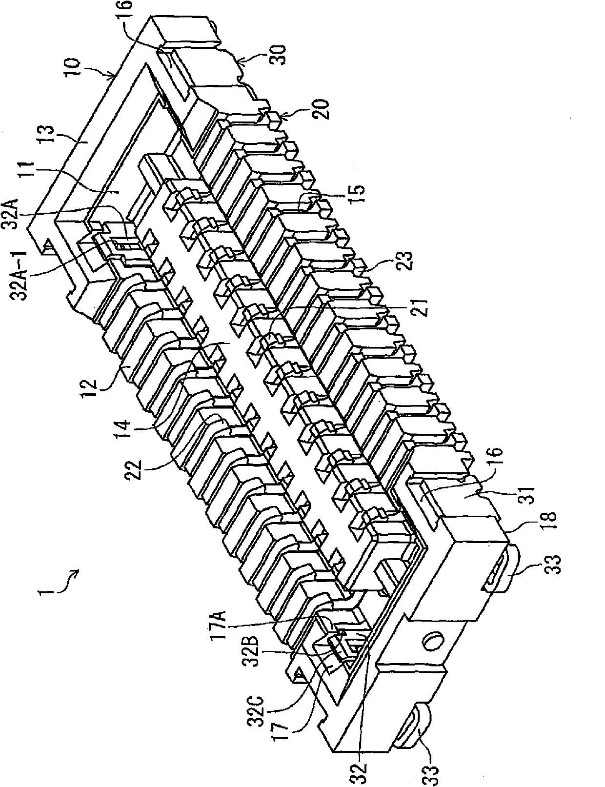
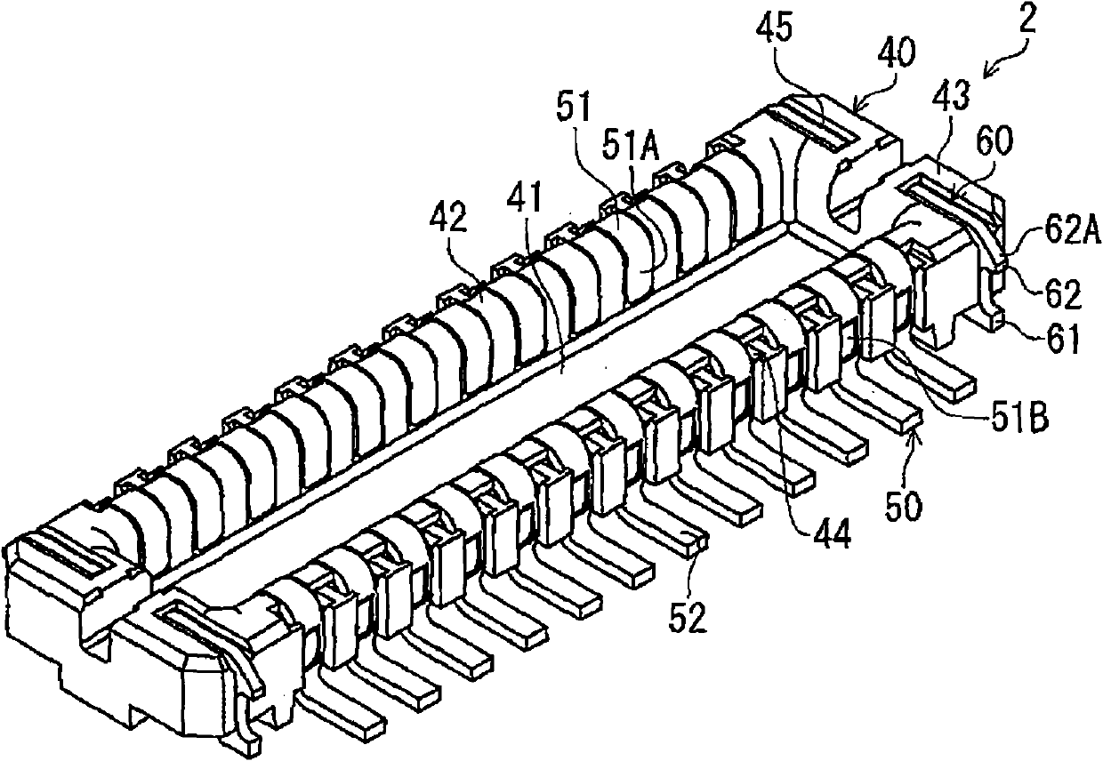
[0040] figure 1 It is a perspective view showing the whole of an electrical connector 1 for a circuit board (hereinafter simply referred to as "connector 1") according to the present embodiment. This connector 1 is an electrical connector disposed on a circuit board (not shown), and has a cover 10 made of an electrical insulating material, such as synthetic resin, into which a mating connector 2 described later is inserted from above. A plurality of terminals 20, the plurality of terminals 20 are arranged and held in the cover 10; a plurality of locking metal parts 30, the plurality of locking metal parts 30 are held in the cover 10 and are matched with the mating connector 2 described later The locking metal piece 60 is locked.

[0041] The cover 10 has a substantially rectangular parallelepiped shape, and is formed with a receiving recess 11 that opens upward, and the mating connector 2 described later is received in the receiving recess 11 from above. The above-mentioned...

no. 2 approach

[0090] The present embodiment is different from the first embodiment in which the displacement of the lock portion is restricted by the restriction portion of the lock metal fitting from the first embodiment in which the displacement of the lock portion is restricted by the restriction protrusion of the cover. The basic configuration of the connector and mating connector in this embodiment is the same as that of the connector and mating connector in the first embodiment; The parts common to those of the first embodiment are denoted by the same reference numerals and description thereof will be omitted. In addition, the locking metal fitting mark will demonstrate the symbol which added "100" to the symbol of the locking metal fitting of 1st Embodiment.

[0091] Image 6 It is a perspective view of the whole lock fitting concerning this embodiment. The locking metal fitting 130 in this embodiment is the same as the locking metal fitting 30 in the first embodiment in terms of b...

no. 3 approach

[0100] The present embodiment is different from the first embodiment in that two lock fitting parts are connected by the bottom plate part. The basic configuration of the connector and mating connector in this embodiment is the same as that of the connector and mating connector in the first embodiment; The parts common to those of the first embodiment are denoted by the same reference numerals and description thereof will be omitted. In addition, the locking metal fitting mark will demonstrate the code|symbol which added "200" to the code|symbol of the locking metal fitting of 1st Embodiment.

[0101] Figure 7 It is a perspective view which shows the whole locking metal fitting which concerns on this embodiment. The lock metal fitting 230 in this embodiment is produced by punching out a metal plate and bending the metal plate in the thickness direction. The locking metal fitting 230 is provided with a held portion 231 , a locking portion 232 , a coupling portion 233 , and ...


PUM


Abstract

The invention provides an electric connector for a circuit substrate. A locking metalwork (30) comprises a retained portion (31) which is disposed at one end of the locking metalwork and is maintained to a cover, a locking portion (32) which is disposed at the other end of the metalwork and can be clamped with the locking portion in a connector imbedding direction, a flexible connection portion (33) which is bended in a manner of connecting the retained portion (31) and the locking portion (32). The connection portion (33) has a first arm portion (33A) and a second arm portion (33B) which are separately disposed in a direction vertical to the connector imbedding direction. During the imbedding of the connector, the retained portion (31) is pressed by the locked portion, the first arm portion (33A) connected to the locking portion (32) elastically moves from a direction vertical to the connector imbedding direction to a direction adjacent to the second arm portion (33B), and thereby the locking portion (32) is clamped with the locked portion.

Description

technical field [0001] The invention relates to an electrical connector for a circuit substrate. Background technique [0002] In the electrical connector arranged on the circuit board, in order to prevent the mating connector from unintentionally falling off, the connector is provided with a locking function. For example, Patent Document 1 discloses a technique in which, among a male-side connector and a female-side connector whose mating direction is perpendicular to the circuit board, the male-side connector has a male-side reinforcing metal piece and the female-side connector is connected to the male-side connector. The device has a female side reinforcement metal piece, and the connectors are prevented from falling off unintentionally by engaging the convex side reinforcement metal piece and the female side reinforcement metal piece in the above-mentioned fitting direction. [0003] The above-mentioned male-side reinforcement metal parts are produced by punching out a ...

Claims


Application Information

Patent Timeline
Patent Type & Authority Applications(China)
IPC IPC(8): H01R13/639H01R12/50
Inventor 后藤雅之绿川和弥细田翔平
Owner HIROSE ELECTRIC GROUP
Why Eureka
Try Eureka