

Composite electric motor
A kind of motor and composite technology, applied in the field of technical motors, can solve problems such as low efficiency and difficult speed regulation, and achieve the effect of high-efficiency structure
- Summary
- Abstract
- Description
- Claims
- Application Information
AI Technical Summary
Problems solved by technology
Method used
Image

Examples
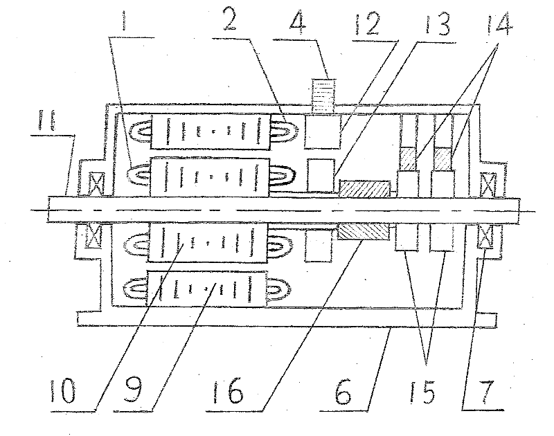
Embodiment 2
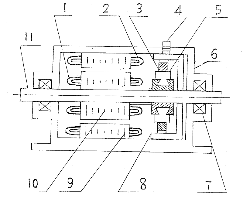
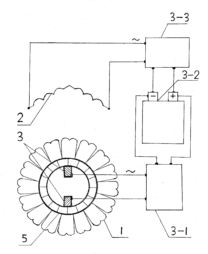
[0014] Embodiment 1 of the present invention: figure 1 and figure 2 Among them, the elements of the stator part include the organic base (6), the stator winding (2), the stator core (9), and the fixed shaft (4); the elements of the rotor part include the rotating shaft (11), the bearing (7), the rotor winding ( 1), the rotor core (10); the elements of the mechanical changer part include the mechanical changer circuit (5), the electric brush (3), and the shelf (8). Adjust the electric brush (3) on the mechanical switching circuit (5) to a position with ideal torque force, fix the electric brush (3) with the fixed shaft (4), so that the electric brush (3) cannot rotate a little . When the alternating current is connected to the stator winding (2), the stator alternating magnetic field is generated and established. In the stator AC magnetic field, the rotor winding (1) induces induced electromotive force and induced current, and the induced electromotive force and induced cur...
PUM
 Abstract
Description
Claims
Application Information