Voltage compensation circuit for constant-current system

A voltage compensation and circuit technology, applied in control/regulating systems, electrical components, regulating electrical variables, etc., can solve problems such as poor effect and no real constant current function, and achieve the effect of improving constant current effect.

Inactive Publication Date: 2011-11-09
MAXIC TECHNOLOGY CORPORATION
View PDF2 Cites 10 Cited by
  • Summary
  • Abstract
  • Description
  • Claims
  • Application Information

AI Technical Summary

Problems solved by technology

image 3 Among them, although the sampled signal contains Vo (the specific sampling value is Vdc minus Vo), the sampled signal does not actually sample the voltage Vo, so the actual implementation effect is relatively poor, and the constant current function is not really realized.

Method used


Image

  • Voltage compensation circuit for constant-current system
  • Voltage compensation circuit for constant-current system
  • Voltage compensation circuit for constant-current system

Examples


Embodiment Construction

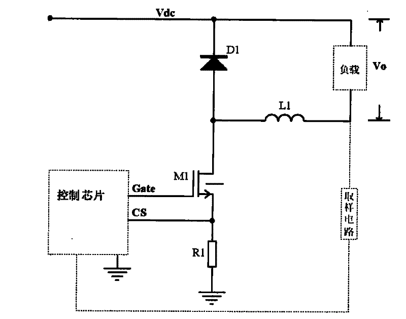
[0033] Figure 4 A structural diagram of a constant current circuit based on voltage compensation according to an embodiment of the present invention. Figure 4 Among them, the constant current circuit includes a control chip 410 , a BUCK topology circuit 420 and a voltage compensation circuit 430 , wherein the voltage compensation circuit 430 includes an output voltage detection circuit 431 and a control circuit 432 .

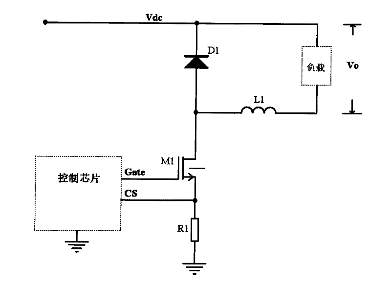
[0034] The BUCK topology circuit 420 includes a load 421 , an inductor L1 , a diode D1 , a switch M1 , and a resistor R1 . Wherein, the load 421 is connected to the diode D1, and the voltage across the load 421 is used as the output terminal voltage Vo; one end of the switch tube M1 is connected to the diode D1, and the other end is connected to the control chip 410 . In one example, the switch tube M1 is a MOS tube. It should be noted that the BUCK topology circuit 420 may be any circuit with a BUCK topology, and is not limited to Figure 4 The connection ...


PUM


Abstract

The invention relates to a voltage compensation circuit and method for a constant-current system. The constant-current system comprises a BUCK topological structure circuit, wherein the BUCK topological structure circuit comprises a load and a switch tube; the output voltage of the constant-current system is the voltage of the two ends of the load; and the voltage compensation circuit is used for generating a control signal which is linearly relevant to the output voltage to control the switch-on and switch-off of the switch tube according to the control signal so as to further keep an arithmetic product of the output voltage and the switch-on time of the switch tube approximately constant to output constant current. Due to the adoption of the voltage compensation method, the constant-current effect of the output current is greatly improved; and the voltage compensation method can be widely applied to an analog integrated circuit which needs to obtain constant current.

Description

technical field [0001] The invention relates to an analog integrated circuit, in particular to a constant current circuit. Background technique [0002] Constant current is also a steady current, and the constant current system is a circuit system that stabilizes the output current or the output average current. The function of the constant current system is to stabilize the output current, no matter how the input voltage and output load change, the output current is always constant. In the traditional constant current system, a sampling resistor is connected in series with the load, and the current signal is converted into a voltage signal and then fed back to the control circuit. However, in some special circuits, such as LED lighting, due to the limitation of product cost, efficiency or internal space, it is impossible to use this traditional constant current system to generate constant current. A commonly used solution at present is to control the on and off time of th...

Claims


Application Information

Patent Timeline
Patent Type & Authority Applications(China)
IPC IPC(8): H02M3/156
Inventor 陈湛郑儒富刘柳胜
Owner MAXIC TECHNOLOGY CORPORATION
Why Eureka
Try Eureka