Adsorption method

A technology of adsorber and adsorption process, which is applied in the field of adsorption and can solve problems such as increased demand for external energy

Inactive Publication Date: 2016-08-03
LINDE AG
View PDF8 Cites 0 Cited by
  • Summary
  • Abstract
  • Description
  • Claims
  • Application Information

AI Technical Summary

Problems solved by technology

Additional external cooling is therefore required, at least temporarily, resulting in an increased external energy requirement

Method used


Image

  • Adsorption method

Examples


Embodiment Construction

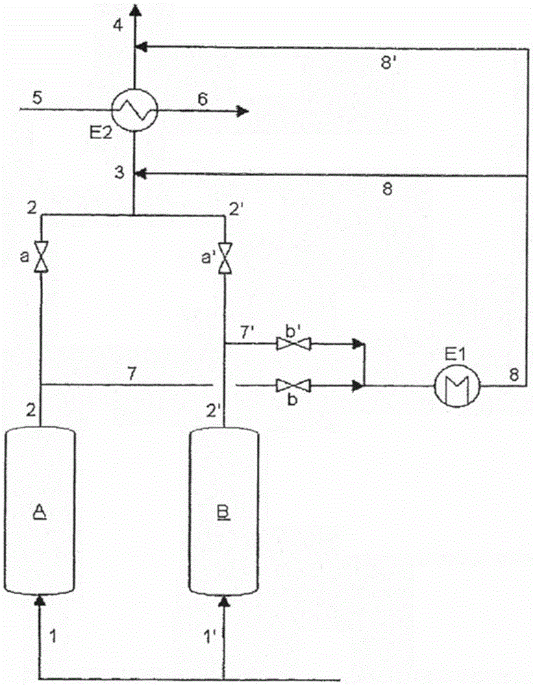
[0012] The adsorption process shown in the drawing takes place in two adsorbers A and B arranged parallel to one another. The process flow is explained below when the regeneration in adsorber B has ended (adsorber A is still in the adsorption phase).

[0013] The main flow of the gas mixture to be separated is supplied via line 1 to adsorber A in the adsorption stage. These are, for example, carbon dioxide-rich gas mixtures, wherein the adsorption process is designed or the adsorption medium is selected in such a way that the adsorption medium is able to bind the carbon dioxide. The largely carbon dioxide-depleted stream is withdrawn from the adsorber A via line 2 in which a regulating valve a is preferably arranged.

[0014] The secondary flow of the gas mixture to be separated is supplied to the adsorber B via line 1 ′ for cooling purposes. After the secondary flow has passed through the adsorber B, it is taken out through a line 2', in which line 2' is preferably also pro...


PUM


Abstract

The method involves carrying out the cooling of the regenerated adsorbent (A,B) to the adsorption temperature with a partial stream of the gas mixture to be analyzed at the end of the regeneration phase. The partial flow of the main stream or the partial stream is deducted, cooled and supplied to the combined stream before or after heat exchange with a medium. The combined flow serves the cooling of the feed gas to be supplied to the Rectisol(RTM: Acid gas removal process) process.

Description

technical field [0001] The invention relates to a method for the separation of gas mixtures by means of an adsorption process, in particular a TSA process, wherein the adsorption process is carried out in at least two adsorbers arranged in parallel to one another, which undergo a time-shifted an adsorption phase and a regeneration phase, at the end of the regeneration phase, the regenerated adsorber is cooled down to the adsorption temperature with a side stream of the gas mixture to be separated, at least during the cooling of said regenerated adsorber, said side stream being connected with the The gas mixture (main flow) led through the adsorber in the adsorption phase merges and the combined stream is heat-exchanged with an optional medium. Background technique [0002] Methods of this type for separating gas mixtures by means of adsorption processes, in particular TSA (Thermal Swing Adsorption) processes, are sufficiently known from the prior art. Such an adsorption pro...

Claims


Application Information

Patent Timeline
Patent Type & Authority Patents(China)
IPC IPC(8): B01D53/02B01D53/047
CPCB01D53/0462B01D53/1437B01D2252/2021B01D2257/504B01D2259/40007B01D2259/402Y02C20/40
Inventor A·泽利格M·贝格W·迈尔
Owner LINDE AG
Why Eureka
Try Eureka