Automatic rivet pulling device

An automatic and mounting frame technology, applied in the field of machining, can solve the problems of poor riveting quality, high labor intensity and low efficiency, and achieve the effect of compact overall structure and size, high versatility and simple control form.

Inactive Publication Date: 2013-04-03
NORTHWESTERN POLYTECHNICAL UNIV
View PDF1 Cites 3 Cited by
  • Summary
  • Abstract
  • Description
  • Claims
  • Application Information

AI Technical Summary

Problems solved by technology

[0004] Aiming at the disadvantages of poor riveting quality, low efficiency, high labor intensity and inability to be integrated into automatic processing parts in the current manual riveting working mode, the present invention proposes an automatic riveting device

Method used


Image

  • Automatic rivet pulling device
  • Automatic rivet pulling device
  • Automatic rivet pulling device

Examples


Embodiment

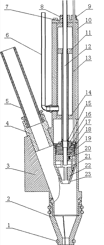
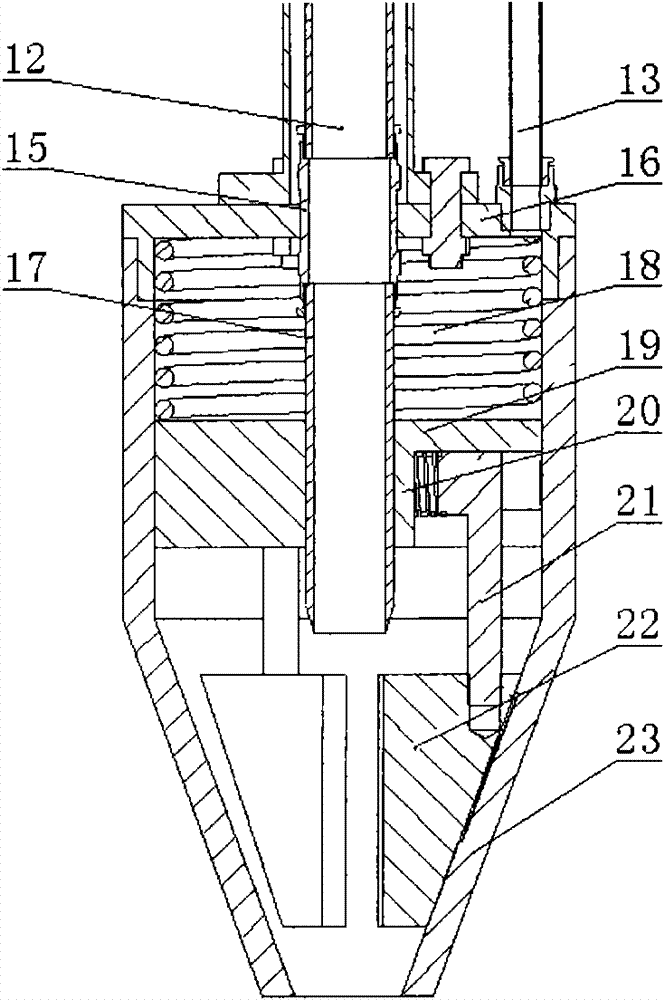
[0027] The automatic riveting device adopted in this embodiment includes a riveting chamber, a riveting chuck, a power unit and a core ejector tube 12 .

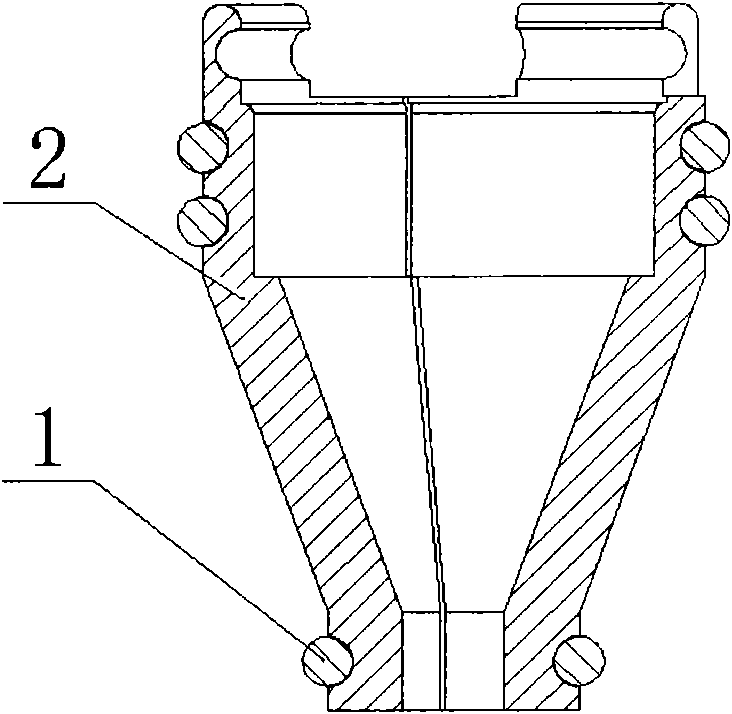
[0028] Refer to attached figure 1 , The riveting cavity includes a shell 3 and a separate collet, wherein the shell 3 has a through hole and an oblique hole, the oblique hole communicates with the through hole, and the central axis of the oblique hole intersects the central axis of the through hole. The through hole is the movement area of ​​the riveting chuck, and the outer end of the inclined hole is used to clamp the joint 4, which communicates with the external high-pressure pneumatic riveting tube 5, so that the rivets enter the inclined hole through the external riveting tube 5 if needed. Obviously, the direction of the inclined hole should be towards the direction of the split collet, so that the fed rivet can be inserted into the split collet. In addition, in order to effectively feed the rivet from the inclined hol...


PUM


Abstract

The invention provides an automatic rivet pulling device which comprises a rivet pulling cavity, a rivet drawing chuck, a power device and a core discharging pipe, wherein the rivet pulling cavity provides a space for the rivet drawing chuck, and rivets are fed in by virtue of an external rivet feeding pipe; driven by the power device, the rivet drawing chuck clamps, pushes and draws the rivets; and finally a drawn rivet mandrel is discharged from the core discharging pipe. By adopting the automatic rivet pulling device provided by the invention, automatic rivet pressing, rivet drawing and core discharging can be carried out under the control of a control system, automatic rivet drawing can be realized, and the automatic rivet pulling device can be integrated into an automatic assembling line. And a corresponding control system adopts a sensor to realize control, thus the control type is simple, convenient and reliable. An elastic clamping piece and a three-jaw structure are adopted, multiple rivets in different specifications can be accepted, and the generality is higher; and the whole structure size is compact, thus the automatic rivet pulling device provided by the invention can be applicable to multiple workplaces.

Description

technical field [0001] The invention relates to the field of mechanical processing, in particular to an automatic riveting device. Background technique [0002] Blind rivets are widely used in automobiles, aviation and other fields. At present, the main method of riveting blind rivets in China is manual riveting, such as using riveting guns and so on. For example, the application number is 200910132222.8, a kind of multifunctional riveting gun disclosed in Chinese invention patent, which can only manually put the blind rivet into the riveting gun, and then perform riveting, and the rivet mandrel after the riveting is freely scattered, both It cannot be integrated into automation components, and it also pollutes the environment. The ordinary manual riveting method also has the disadvantages of riveting quality being affected by human factors, poor working conditions, and low efficiency, and it is difficult to meet the requirements of higher surface processing accuracy in the...

Claims


Application Information

Patent Timeline
Patent Type & Authority Patents(China)
IPC IPC(8): B21J15/38
CPCB21J15/043B21J15/32
Inventor 秦现生田青山杨占锋谭小群李树军沈东莹刘寰
Owner NORTHWESTERN POLYTECHNICAL UNIV
Why Eureka
Try Eureka