Take-up and pay-off device for belt winding mechanism of belt conveyor

The technology of a belt conveyor and a belt winding mechanism is applied in the field of the belt winding and unwinding device of the belt winding mechanism, which can solve the problem of unreasonableness, increase the work intensity and working time, and load the coil that cannot be rolled into the mine car. And other issues

Inactive Publication Date: 2011-11-16
XUZHOU WUYANG TECH
View PDF9 Cites 5 Cited by
  • Summary
  • Abstract
  • Description
  • Claims
  • Application Information

AI Technical Summary

Problems solved by technology

[0002] At present, most of the recycling of the belt conveyor belt is done manually, which increases the working intensity and working time of the operation.
In the prior art, although the hydraulic retractable belt device of the fixed belt conveyor (authorization number: CN201458225U) has improved the above shortcomings to a certain extent, there are still unreasonable points
For example, the distance between the center of the belt conveyor and the center of the track of the mining trolley is different. The existing belt retracting device cannot directly load the coiled coil on the mine trolley after sending the coil out from under the conveyor body. , but it needs to be loaded on the mine car through a second transfer; the existing tape-rewinding device is not equipped with a guide device, and during the tape-winding process, it is necessary to reduce the tape-winding speed, constantly adjust the cantilever, and rely on manual work to ensure that the tape roll neat and tight
In this way, it is a waste of time and manpower

Method used


Image

  • Take-up and pay-off device for belt winding mechanism of belt conveyor
  • Take-up and pay-off device for belt winding mechanism of belt conveyor
  • Take-up and pay-off device for belt winding mechanism of belt conveyor

Examples


Embodiment Construction

[0013] The present invention will be further described below in conjunction with accompanying drawing.

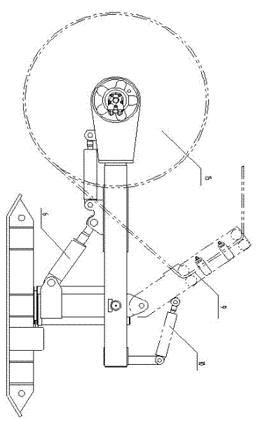
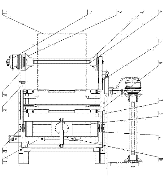
[0014] like figure 1 , figure 2 and image 3 As shown, the present invention includes a winding motor 1, coupling disc I2, coupling disc II3, reel 4, lifting cylinder 6, chassis 7, support base 8 and rotating cylinder 11; also includes moving cantilever 14, static cantilever 13, cantilever telescopic cylinder 5. The guide device 9 and the guide cylinder 10; the support base 8 is installed on the chassis 7, and is connected by the rotating cylinder 11; the static cantilever 13 is installed on the support base 8, and is connected by the lifting cylinder 6; the static cantilever 13 is connected by the cantilever telescopic cylinder 5 Connect the moving cantilever 14; the moving cantilever 14 is equipped with a winding motor 1, connecting disc I2, connecting disc II3, reel 4, cantilever telescopic oil cylinder 5, guide device 9 and guiding oil cylinder 10; reel 4 passes thro...


PUM


Abstract

The invention discloses a take-up and pay-off device for a belt winding mechanism of a belt conveyor, which belongs to the technical field of the take-up and pay-off devices. The take-up and pay-off device comprises a belt winding motor, a coupling disk I, a coupling disk II, a winding shaft, a lifting oil cylinder, a chassis, a support seat and a rotating oil cylinder, as well as a moving cantilever, a fixed cantilever, a cantilever telescopic oil cylinder, a guide device and a guide oil cylinder, wherein the support seat is mounted on the chassis and connected through the rotating oil cylinder; the fixed cantilever is mounted on the support seat and connected through the lifting oil cylinder; the fixed cantilever is connected with the moving cantilever through the cantilever telescopic oil cylinder; the belt winding motor, the coupling disk I, the coupling disk II, the winding shaft, the cantilever telescopic oil cylinder, the guide device and the guide oil cylinder are mounted on the moving cantilever; the winding shaft is connected with the moving cantilever through the coupling disk I and the coupling disk II; and the guide device is connected with the fixed cantilever through the guide oil cylinder. The take-up and pay-off device has the benefits that the take-up and pay-off device can coil a conveyor belt tidily and closely without performing any adjustment during the belt winding process and can smoothly send a belt coil onto a mine flat-bed truck after completing the belt winding.

Description

technical field [0001] The invention relates to a belt retracting and unwinding device for a winding mechanism, especially suitable for automatic retracting and unwinding of a retractable belt conveyor, and belongs to the technical field of belt retracting and unwinding devices. Background technique [0002] At present, the recovery of the belt conveyor belt is mostly done manually, which increases the working intensity and working time of the operation. In the prior art, although the hydraulic belt retracting and unwinding device of the fixed belt conveyor (authorization number: CN201458225U) has improved the above-mentioned deficiencies to a certain extent, there are still unreasonable points. For example, the distance between the center of the belt conveyor and the center of the track of the mining trolley is different. The existing belt retracting device cannot directly load the coiled coil on the mine trolley after sending the coil out from under the conveyor body. , b...

Claims


Application Information

Patent Timeline
Patent Type & Authority Applications(China)
IPC IPC(8): B65H75/38
Inventor 蔡敏
Owner XUZHOU WUYANG TECH
Why Eureka
Try Eureka