
Optical diaphragm

A technology of optical film and thin film, which is applied in optics, nonlinear optics, light sources, etc., can solve the problem that light from large angles cannot be effectively used, and achieve the effects of improving light utilization, reducing costs, and increasing brightness

Inactive Publication Date: 2011-11-16
AU OPTRONICS CORP
View PDF0 Cites 0 Cited by
  • Summary
  • Abstract
  • Description
  • Claims
  • Application Information

AI Technical Summary

Problems solved by technology

Generally, the display uses an optical film to concentrate the light to a positive viewing angle of ±35° to increase brightness. The traditional optical film is a prism structure with a single continuous angle. The light is refracted by the angle of the prism and then emerges. cannot be used effectively

Method used


Image

  • Optical diaphragm
  • Optical diaphragm
  • Optical diaphragm

Examples


Embodiment Construction

[0018] The specific implementation manners of the present invention will be described in further detail below with reference to the accompanying drawings.

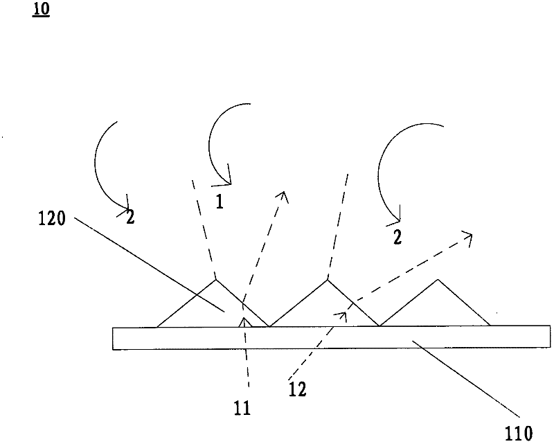
[0019] figure 1 A schematic structural view of an optical film in the prior art is shown. refer to figure 1 , the optical film 10 includes a base film 110 and a plurality of prisms 120 . Wherein, a plurality of prisms 120 are connected to the substrate film 110, and each prism 120 has a single fixed angle and is connected with each other to form an array. The substrate film 110 is divided into an active area 1 and an inactive area 2, the active area 1 is located in the direction of the normal viewing angle, and the ineffective area 2 is located in the direction of the non-orthogonal viewing angle. Such as figure 1 As shown, the light 11 enters the prism 120 after being reflected, and is refracted by the prism 120 to come out and fall into the effective area 1 . However, the light 12 with a large viewing angle enters t...


PUM


Abstract

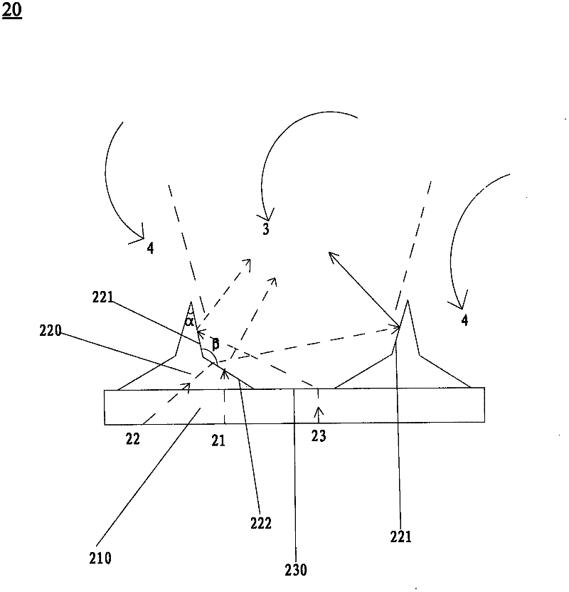
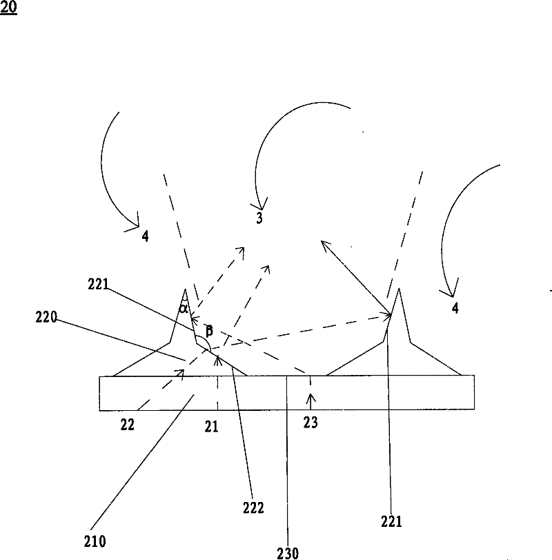
The invention provides an optical diaphragm. The optical diaphragm is characterized by comprising a base material thin film and a plurality of prisms, wherein the plurality of prisms are connected to the base material thin film in an array mode; each of the plurality of prisms has a pair of lower prism surfaces and a pair of upper prism surfaces; the upper prism surfaces are connected with the lower prism surfaces correspondingly; an included angle is formed between each upper prism surface and the corresponding lower prism surface; an interval is formed between two adjacent prisms; and a section of upper surface of the base material thin film is exposed. By adoption of the optical diaphragm, light utilization rate can be improved, the brightness of a product is improved, and cost can be reduced.

Description

technical field [0001] The invention relates to an optical film, in particular to an optical film capable of increasing the brightness of a liquid crystal display. Background technique [0002] Liquid crystal display (Liquid Crystal Display, abbreviated as LCD) has the characteristics of high quality, thin thickness, low power consumption and low radiation. It has been widely used in information technology, multimedia technology and other fields, and has gradually become the mainstream flat display device. Because the liquid crystal material itself does not emit light, it is necessary to configure a backlight module for the display screen to provide an additional light source. Since light-emitting diodes (LEDs) have the characteristics of no pollution, long life, shock resistance, impact resistance and no pollution, LEDs have become mainstream as a backlight source for liquid crystal displays (LCDs) at present. [0003] In the backlight module, the light from the LED enters...

Claims


Application Information

Patent Timeline
IPC IPC(8): G02B5/04G02F1/13357F21V5/02F21Y101/02
Inventor 杨文虎陈圣杰
Owner AU OPTRONICS CORP
Learn More