
Bearer establishing method, relay node and base station

A technology for relay node and bearer establishment, applied in electrical components, wireless communication, connection management, etc., to reduce the signaling interaction process

Inactive Publication Date: 2011-11-16
CHINA ACAD OF TELECOMM TECH
View PDF2 Cites 20 Cited by
  • Summary
  • Abstract
  • Description
  • Claims
  • Application Information

AI Technical Summary

Problems solved by technology

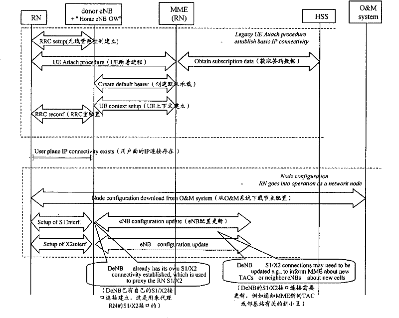
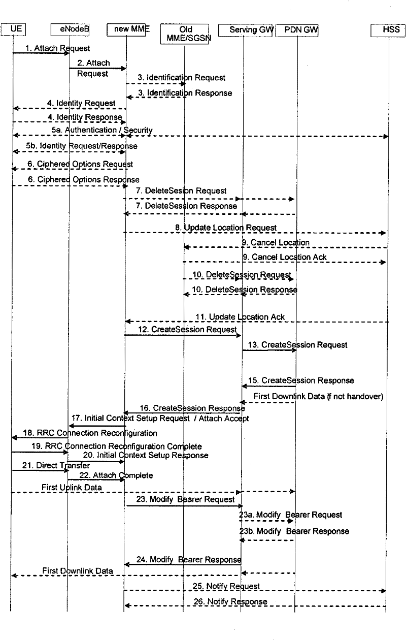
[0019] The technical problem solved by the present invention is to provide a bearer establishment method, relay node and base station to solve the problem of establishing bearer between RN and DeNB after radio link failure or RRC connection re-establishment failure

Method used


Image

  • Bearer establishing method, relay node and base station
  • Bearer establishing method, relay node and base station
  • Bearer establishing method, relay node and base station

Examples


Embodiment 1

[0074] Figure 8 It is a schematic diagram of the implementation flow of the bearer establishment method in Embodiment 1, as shown in the figure, which may include the following steps:

[0075] Step 801. After the RN connects to a Donor cell each time, the NAS saves the ID information of the cell.

[0076] In step 802, the NAS obtains cell identification information.

[0077] During implementation, when selecting a cell, the RN may read the system information broadcast by the cell, and obtain the cell identity information therefrom. Then the AS reports the identification information of the selected cell to the NAS. The cell identification information includes TAC (TrackingArea Code, tracking area code), Cell ID and so on.

[0078] Step 803: Initiate different NAS procedures according to whether the DeNB changes to restore the connection between the RN and the DeNB.

[0079] In implementation, the first 20 bits in the Cell ID are the eNB ID, and the NAS can judge whether th...

Embodiment 2

[0088] Figure 10 It is a schematic diagram of the implementation flow of the bearer establishment method in Embodiment 2, as shown in the figure, which may include the following steps:

[0089] Step 1001, the AS acquires cell identity information.

[0090] When the RN selects a cell, it reads the system information broadcast by the cell, and obtains the cell identification information therefrom. The cell identification information includes TAC, Cell ID, etc.;

[0091] In step 1002, the AS determines whether the DeNB has changed and reports it to the NAS.

[0092] After the AS obtains the cell information, the first 20 bits of the Cell ID are the eNB ID, and the AS can judge whether the DeNB has changed according to the eNB ID. The AS reports the selected cell identity information and / or the indication of whether the DeNB has changed to the NAS;

[0093] Step 1003, the NAS initiates different NAS procedures according to the instruction to restore the connection between the...


PUM


Abstract

The invention discloses a bearer establishing method, a relay node and a base station. The method comprises the following steps: after a radio link fails or radio resource control connection reconstruction fails, a non-access stratum of the relay node determines whether a donor evolved base station is the same as a donor evolved base station which is connected with before failure; when the donor evolved base station is the same as the donor evolved base station which is connected with before failure, a service request process is initiated and an original evolved packet system bearer is activated; and, when the donor evolved base station is not the same as the donor evolved base station which is connected with before failure, an attachment process is initiated and a bearer is established. According to the method disclosed by the invention, in the event that the donor evolved base station is not changed, the relay node can be used for establishing a connection with the donor evolved base station as soon as possible; therefore, the signalling interactive process is reduced; in the event that the donor evolved base station is changed, the problem of incapability of changing a packet data gateway in the prior art can be solved; and, because of adoption of the traditional parameters in the implementation, the realizing complexity is low.

Description

technical field [0001] The invention relates to wireless communication technology, in particular to a bearer establishment method, a relay node and a base station. Background technique [0002] In future mobile communication systems, such as B3G (Beyond Third Generation) or LTE-A (Long Term Evolution-Advance, long-term evolution upgrade), the system will provide higher peak data rate and cell throughput, and also requires Larger bandwidth, currently there is very little unallocated bandwidth below 2GHz, and part or all of the bandwidth required by the B3G system can only be found in higher frequency bands, such as above 3GHz. The higher the frequency band, the faster the attenuation of radio wave propagation and the shorter the transmission distance. Therefore, in the same coverage area, to ensure continuous coverage, more base stations are required. Since base stations usually have a higher cost, this will undoubtedly increase the cost of network deployment. In order to so...

Claims


Application Information

Patent Timeline
Patent Type & Authority Applications(China)
IPC IPC(8): H04W76/02H04W76/06
Inventor 杨义汪颖鲍炜
Owner CHINA ACAD OF TELECOMM TECH
Learn More