Machine motion trajectory measuring device, numerically controlled machine tool, and machine motion trajectory measuring method

A motion trajectory, mechanical motion technology, applied in measuring devices, feeding devices, digital control, etc., can solve problems such as the inability to measure motion trajectories

Active Publication Date: 2011-11-16
MITSUBISHI ELECTRIC CORP
View PDF11 Cites 31 Cited by
  • Summary
  • Abstract
  • Description
  • Claims
  • Application Information

AI Technical Summary

Problems solved by technology

[0013] In the method described in Patent Document 1, there is a problem that only the trajectory of a circular arc with a defined radius can be measured, for example, the movement trajectory of a corner that is likely to vibrate in the machine cannot be measured.

Method used


Image

  • Machine motion trajectory measuring device, numerically controlled machine tool, and machine motion trajectory measuring method
  • Machine motion trajectory measuring device, numerically controlled machine tool, and machine motion trajectory measuring method
  • Machine motion trajectory measuring device, numerically controlled machine tool, and machine motion trajectory measuring method

Examples


Embodiment approach

[0040] Next, taking the measurement of the mechanical movement trajectory of a numerically controlled machine tool as an example, the mechanical movement trajectory measurement device according to the embodiment of the present invention will be described with reference to the drawings. In addition, this invention is not limited to the following description.

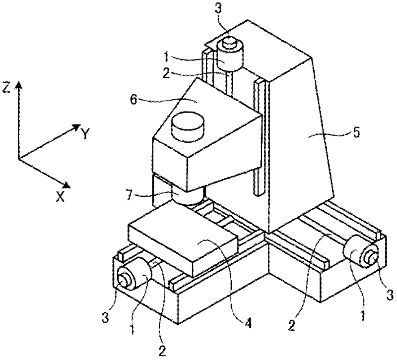
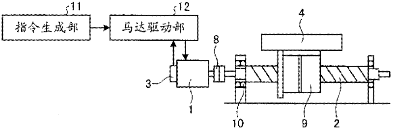
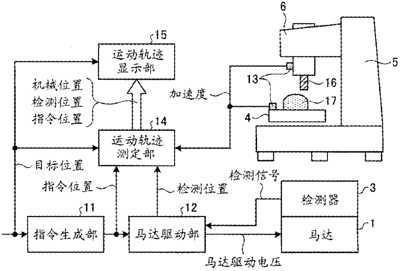
[0041] figure 1 An example of the form of a CNC machine tool is shown. There are a plurality of movable shafts that guide motion in the X-axis, Y-axis, and Z-axis directions, and each movable shaft is driven by a drive mechanism composed of a motor 1 and a feed screw 2 . The rotation angle of the motor is detected by the rotation angle detector 3 and fed back to the control device. As a driving method, a linear motor may be used instead of the motor 1 and the feed screw 2 , and a linear scale may be used instead of the rotation angle detector 3 .

[0042] exist figure 1 In the numerically controlled machine tool of th...


PUM


Abstract

The present invention provides a machine motion trajectory measuring device, a numerically controlled machine tool, and a machine motion trajectory measuring method. The machine motion trajectory measuring device is for measuring the trajectory of motion of a machine, adapted for use in a device for controlling the position of the machine in such a manner that a detected position which is obtained by converting a motor rotation angle into the position of the machine is fed back to drive each of motors (1) for movable shafts so that the detected position follows a commanded position. The machine motion trajectory measuring device is provided with an acceleration meter (13) which measures the acceleration of the machine, and a motion trajectory measuring unit (14) which measures the trajectory of motion of the machine by obtaining the position of the machine through double integration of the acceleration and correcting the machine position so that the profile of the position of the machine coincides with the profile of an estimated position estimated by a model which simulates the response of the position of the machine to the commanded position or with the profile of the detected position.

Description

technical field [0001] The invention relates to a device for measuring the motion track of a machine, in particular to a device for measuring the motion track of a machine in a numerically controlled machine tool and a robot. Background technique [0002] In CNC machine tools and robots, motors are driven to move the machine along multiple movable axes, and the position of the machine is controlled as faithfully as possible to the commanded position. In this case, an error occurs between the command position and the actual machine position due to mechanical vibration or frictional force when the direction of motion is reversed, causing damage to the machined surface, for example. When such a problem occurs, measure the movement trajectory of the machine, find out the cause of the problem, and adjust various parameters of the controller that controls the motor. A variety of methods are known for measuring and displaying the machine motion locus for this purpose. [0003] Th...

Claims


Application Information

Patent Timeline
Patent Type & Authority Applications(China)
IPC IPC(8): B23Q17/00G01B21/00G05B19/18
CPCG05B2219/43072G05B2219/41233B23Q5/40G05B19/19B23Q17/22B23Q5/28
Inventor 左藤隆太长冈弘太朗佐藤智典
Owner MITSUBISHI ELECTRIC CORP
Why Eureka
Try Eureka