Heat exchanger and method for manufacturing same

A manufacturing method and heat exchanger technology, applied in the direction of heat exchanger shell, indirect heat exchanger, heat exchanger type, etc., can solve problems such as inability to ensure working space, inability to block components to heat up, large liquid reservoir, etc., to achieve Effects of improving pressure resistance, preventing heat damage, and improving brazeability

Inactive Publication Date: 2011-11-16
CALSONIC KANSEI CORP
View PDF9 Cites 11 Cited by
  • Summary
  • Abstract
  • Description
  • Claims
  • Application Information

AI Technical Summary

Problems solved by technology

[0005] That is, it is impossible to secure a working space for joining the blocking member
[0006] In addition, the case of the heat exchanger may be deformed by the heat of the obturating members when they are engaged
[0007] In addition, due to the large thermal mass of the reservoir, it is not possible to heat up the obturator member as desired, so bonding takes time

Method used


Image

  • Heat exchanger and method for manufacturing same
  • Heat exchanger and method for manufacturing same
  • Heat exchanger and method for manufacturing same

Examples


Embodiment 1

[0048] Next, the heat exchanger and its manufacturing method according to Embodiment 1 of the present invention will be described with reference to the drawings.

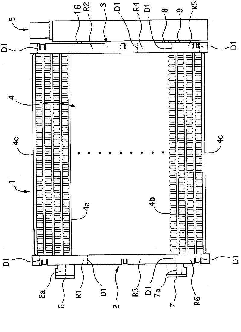
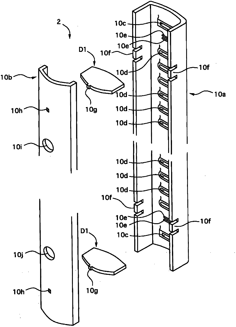
[0049] figure 1is a front view showing the heat exchanger of Example 1, figure 2 It is an exploded perspective view of the box used in the heat exchanger of Example 1, image 3 is a perspective view of the box, Figure 4 yes figure 2 , image 3 The exploded perspective view of the box, Figure 5 is a perspective view of the box.

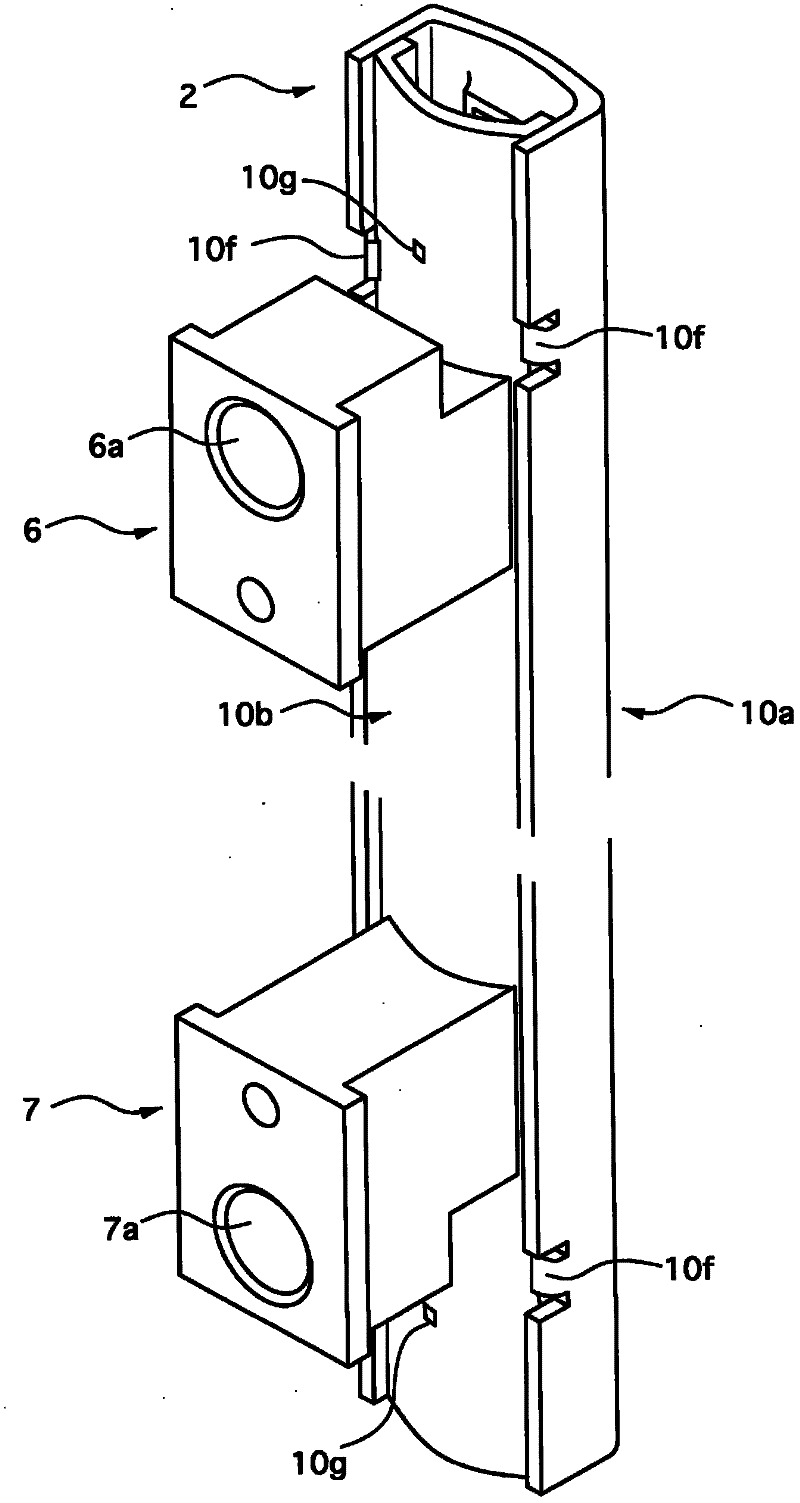
[0050] Figure 6 It is an exploded perspective view of the liquid reservoir used in the heat exchanger of Example 1, Figure 7 is a perspective view of the reservoir, Figure 8 It is an exploded perspective view of the intermediate member and the liquid reservoir of Embodiment 1, Figure 9 is description Figure 6 , Figure 7 A side sectional view of the lower interior of the reservoir, Figure 10 yes Figure 9 Cutaway view of the S10-S10.

[0051] Figure 11 is descriptio...

Embodiment 2

[0207] Next, the heat exchanger and its manufacturing method according to Embodiment 2 of the present invention will be described with reference to the drawings.

[0208] In Embodiment 2, the same reference numerals are assigned to the same constituent members as in Embodiment 1, and descriptions of these members are omitted, and only differences are described in detail.

[0209] Figure 25 It is a figure explaining the high-frequency induction heating in the heat exchanger of Example 2 and its manufacturing method.

[0210] Such as Figure 25 As shown, in the heat exchanger and its manufacturing method of Example 2, a black body paint 50 is applied in advance near the junction of the closing member 15, and an infrared temperature sensor 51 capable of measuring the surface temperature of the black body paint 50 is installed.

[0211] In addition, the temperatures detected by the infrared temperature sensor 51 are sequentially sent to the controller 33 .

[0212] In addition...

Embodiment 3

[0223] Next, the heat exchanger and its manufacturing method according to Embodiment 3 of the present invention will be described with reference to the drawings.

[0224] In the heat exchanger and its manufacturing method of Example 3, the same reference numerals are assigned to the same components as those of Example 1, and description thereof will be omitted, and only differences will be described in detail.

[0225] Figure 26 It is a perspective view of the accumulator used in the heat exchanger of Example 3.

[0226] Such as Figure 26 As shown, in the heat exchanger of Example 3, the overall length of the first divided member 11 of the accumulator 5 is formed much shorter than that of the second divided member 12 .

[0227] In addition, a bracket member 60 having the same shape as the first divided member 11 but shorter than the first divided member 11 is brazed at a position corresponding to the holding member 16 on the outer periphery of the second divided member 12 ...


PUM


Abstract

A heat exchanger (1) includes: a pair of tanks (2, 3) arranged at a predetermined interval; a plurality of tubes (4a) having both end portions communicably connected to the pair of tanks (2, 3); a prolonged liquid container (5) which is arranged adjacent to the tank (3) and communicably connected to the tank (3); a containing member (20) contained in the liquid container (5); an upper opening end portion (13b) having an opening of a reduced diameter at one side in the longitudinal direction of the liquid container (5); and a closing member (15) which closes the upper opening end portion (13b). The entire heat exchanger (1) excluding the containing member (20) and the closing member (15) is integrally formed by a soldering process. After the soldering process, the containing member (20) is inserted from the upper opening end portion (13b) into the liquid container (5). After the insertion and arrangement of the containing member (20), the closing member (15) is bonded to the upper opening end portion (13b) by a soldering process.

Description

technical field [0001] The present invention relates to heat exchangers and methods for their manufacture. Background technique [0002] As a conventional heat exchanger, there is known a structure in which a desiccant is inserted into a reservoir and the inside of the reservoir is sealed with a closing member (see Patent Document 1). [0003] Patent Document 1: Japanese Patent Application Laid-Open: No. 8-110125 [0004] However, in conventional heat exchangers, when improving the pressure resistance of the accumulator, the closing member is joined to the opening end of the accumulator by, for example, welding. At this time, since the liquid receiver is very close to the tank of the heat exchanger, the problems listed below arise. [0005] That is, a working space for joining the blocking member cannot be ensured. [0006] In addition, the tank of the heat exchanger may be deformed by the heat of the obturating members when they are joined. [0007] In addition, since t...

Claims


Application Information

Patent Timeline
Patent Type & Authority Applications(China)
IPC IPC(8): F25B39/04B23K1/00B23K1/002F25B43/00F28F9/02F28F9/26B23K101/14
CPCF28F9/0243F25B2339/0446F28F2220/00F28F9/0278F25B2339/0442F28F19/01F25B43/003B23K2201/14B23K1/203B23K1/002F28D1/0535F28F9/0209F28F9/0229B23K1/0012B23K1/008F25B2339/0441F28F9/0251B23K2101/14F25B39/04Y10T29/4935
Inventor 竹间浩河合嘉宏船津拓未山崎真
Owner CALSONIC KANSEI CORP
Why Eureka
Try Eureka