Heat Exchanger

一种换热器、贮液器的技术,应用在换热器外壳、间接换热器、换热器类型等方向,能够解决无法闭塞构件升温、无法确保作业空间、贮液器热质量大等问题,达到提高耐压性、防止热损伤、提高钎焊性的效果

Active Publication Date: 2013-05-08
CALSONIC KANSEI CORP
View PDF7 Cites 5 Cited by
  • Summary
  • Abstract
  • Description
  • Claims
  • Application Information

AI Technical Summary

Problems solved by technology

[0006] That is, it is impossible to secure a working space for joining the blocking member
[0007] In addition, the case of the heat exchanger may be deformed by the heat of the obturating members when they are engaged
[0008] Also, due to the large thermal mass of the reservoir, the occlusive member cannot be heated up as desired, so engagement takes time

Method used


Image

  • Heat Exchanger
  • Heat Exchanger
  • Heat Exchanger

Examples


Embodiment 1

[0049] Hereinafter, the heat exchanger and its manufacturing method according to Embodiment 1 of the present invention will be described based on the drawings.

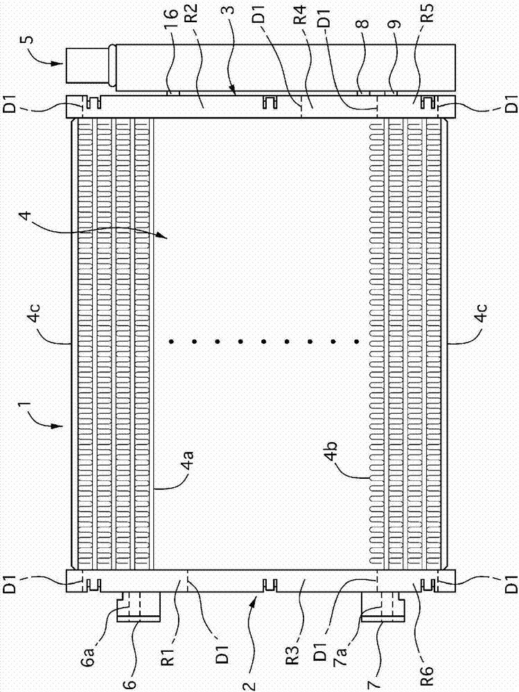
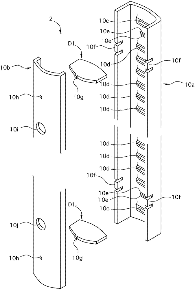
[0050] figure 1 Is a front view showing the heat exchanger of Example 1, figure 2 It is an exploded perspective view of the box used in the heat exchanger of Example 1, image 3 Is a three-dimensional view of the box, Figure 4 Yes figure 2 , image 3 The exploded perspective view of the box, Figure 5 It is a perspective view of the box.

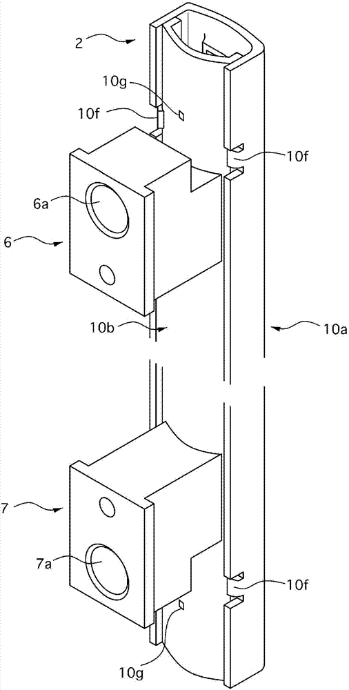
[0051] Image 6 It is an exploded perspective view of the accumulator used in the heat exchanger of Example 1, Figure 7 Is a three-dimensional view of the reservoir, Figure 8 It is an exploded perspective view of the intermediate member and the reservoir of Example 1, Picture 9 Is description Image 6 , Figure 7 Side sectional view of the lower interior of the reservoir, Picture 10 Yes Picture 9 Sectional view of S10-S10.

[0052] Picture 11 Is description Image 6 , Figure 7 Sid...

Embodiment 2

[0209] Hereinafter, a heat exchanger and its manufacturing method according to Embodiment 2 of the present invention will be explained based on the drawings.

[0210] In the second embodiment, the same reference numerals are given to the same constituent members as in the first embodiment, and the description of the members is omitted, and only the differences are described in detail.

[0211] Figure 25 It is a figure explaining the high frequency induction heating in the heat exchanger of Example 2 and its manufacturing method.

[0212] Such as Figure 25 As shown, in the heat exchanger and the manufacturing method of the second embodiment, the black body paint 50 is applied to the vicinity of the junction of the closing member 15 in advance, and an infrared temperature sensor 51 capable of measuring the surface temperature of the black body paint 50 is provided.

[0213] In addition, the temperature detected by the infrared temperature sensor 51 is sequentially sent to the controlle...

Embodiment 3

[0225] Hereinafter, a heat exchanger and its manufacturing method according to Embodiment 3 of the present invention will be described based on the drawings.

[0226] In the heat exchanger of the third embodiment and the manufacturing method thereof, the same constituent members as those of the first embodiment are denoted by the same reference numerals and the description thereof is omitted, and only the differences are described in detail.

[0227] Figure 26 It is a perspective view of the accumulator used in the heat exchanger of Example 3.

[0228] Such as Figure 26 As shown, in the heat exchanger of Example 3, the total length of the first divided member 11 of the accumulator 5 is formed to be significantly shorter than the second divided member 12.

[0229] In addition, a bracket member 60 having the same shape as the first divided member 11 but shorter than the first divided member 11 is brazed at a position corresponding to the holding member 16 on the outer periphery of the ...


PUM


Abstract

A heat exchanger 1 includes a pair of tanks 2 and 3 arranged a certain distance apart from each other, a plurality of tubes 4a whose both end portions are connected with the pair of tanks 2 and 3, a long receiver tank 5 arranged along and adjacently to the tank 3 and communicatably connected with the tank 3, and a reception member 20 contained in the receiver tank 5. An upper opening end portion 13b has an opening portion at one side in a longitudinal direction of the receiver tank 5 and having a reduced diameter, and a block member 15 blocks the upper opening end portion 13b. An entire of the heat exchanger 1 except the reception member 20 and the block member 15 are integrally formed by a brazing process. The reception member 20 is inserted through the upper opening end portion 13b and arranged in the receiver tank 5 after the brazing process, and then the block member 15 is joined by brazing with the upper opening end portion 13b after the reception member 20 is inserted and arranged therein.

Description

[0001] The present invention is a divisional application with the application number of 200980150564.0, the filing date of December 7, 2009, the title of the invention "heat exchanger and its manufacturing method", and the international application number PCT / JP2009 / 070448. Technical field [0002] The invention relates to heat exchangers. Background technique [0003] As a conventional heat exchanger, there is known a structure in which a desiccant is inserted into a reservoir and the inside of the reservoir is sealed with a blocking member (refer to Patent Document 1). [0004] Patent Document 1: Japanese Patent Application Publication No. 8-110125 [0005] However, in the conventional heat exchanger, when improving the pressure resistance of the reservoir, the closing member is joined to the opening end of the reservoir by welding, for example. At this time, because the reservoir and the heat exchanger box are very close, the following problems will occur. [0006] That is, it is i...

Claims


Application Information

Patent Timeline
Patent Type & Authority Applications(China)
IPC IPC(8): F28D1/053F28F9/02B23K1/00B23K1/002B23K1/008B23K1/20
CPCB23K1/002F25B2339/0446B23K1/008B23K1/0012F25B2339/0442F28F9/0209F25B2339/0441F28F9/0229F28F9/0278B23K2201/14B23K1/203F25B43/003F28D1/0535F28F19/01F28F9/0251F28F2220/00F28F9/0243B23K2101/14F25B39/04Y10T29/4935
Inventor 竹间浩河合嘉宏船津拓未山崎真
Owner CALSONIC KANSEI CORP
Why Eureka
Try Eureka