Medical needle-holding forceps

A technology of needle-holding forceps and forceps handle, which is applied in the field of medical needle-holding forceps, which can solve the problems of difficult suturing, serious personal injury to patients, and high difficulty of surgery, and achieve the effect of being easy to use and control, and reducing the difficulty of surgical operation

Inactive Publication Date: 2011-11-23
李宝童
View PDF3 Cites 12 Cited by
  • Summary
  • Abstract
  • Description
  • Claims
  • Application Information

AI Technical Summary

Problems solved by technology

[0002] Medical needle holders are commonly used medical instruments for surgical operations. They are used to hold medical sutures and suture wounds of patients. When the medical needle holders in the prior art are used to hold medical suture needles, their holding angle and orientation are The handle of the pliers is of a single form and cannot be adjusted. When suturing wounds with different positions and orientations, in order to achieve the required suture angle, the operator often needs to adjust the way he holds the needle forceps or even his body standing posture, which makes suturing difficult. Larger, and the medical needle-holding forceps of the prior art is only suitable for suturing the wound on the human body surface, and when suturing the wound located in the deep part of the human body, it is necessary to cut a large enough incision on the human body and remove the tissues in the body. Free to provide the space required for the suturing movement of the needle holder. The entire operation process needs to be performed in multiple steps and requires the cooperation of multiple people to complete the operation, which makes the operation difficult, takes a long time, and causes great personal injury to the patient.

Method used


Image

  • Medical needle-holding forceps
  • Medical needle-holding forceps
  • Medical needle-holding forceps

Examples


Embodiment Construction

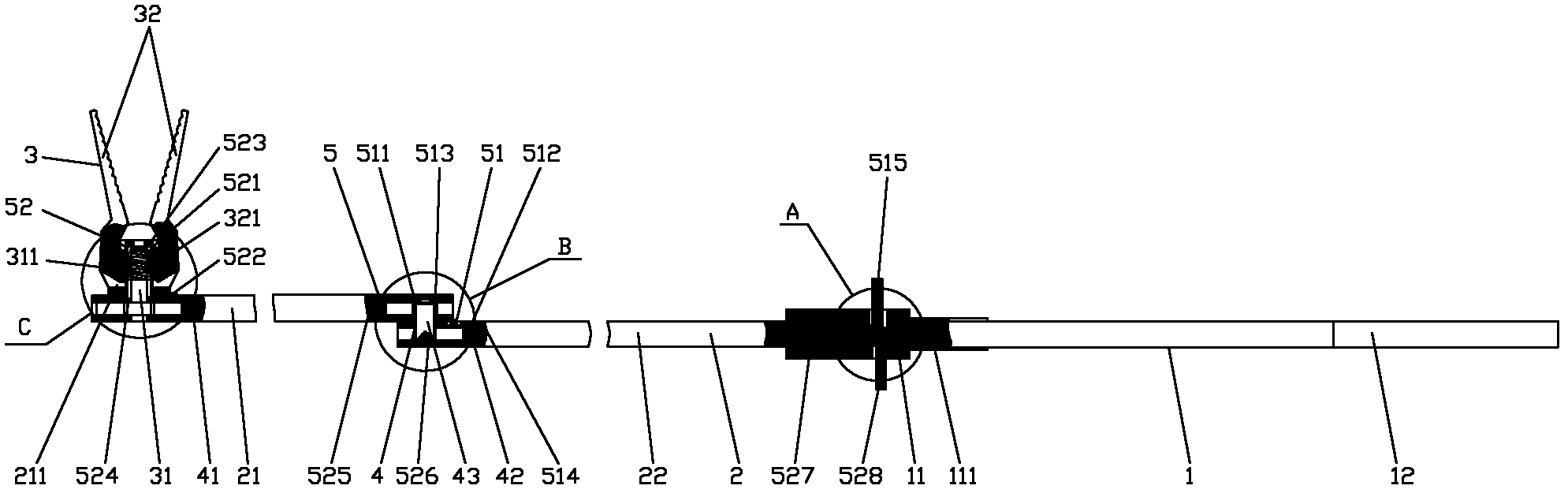
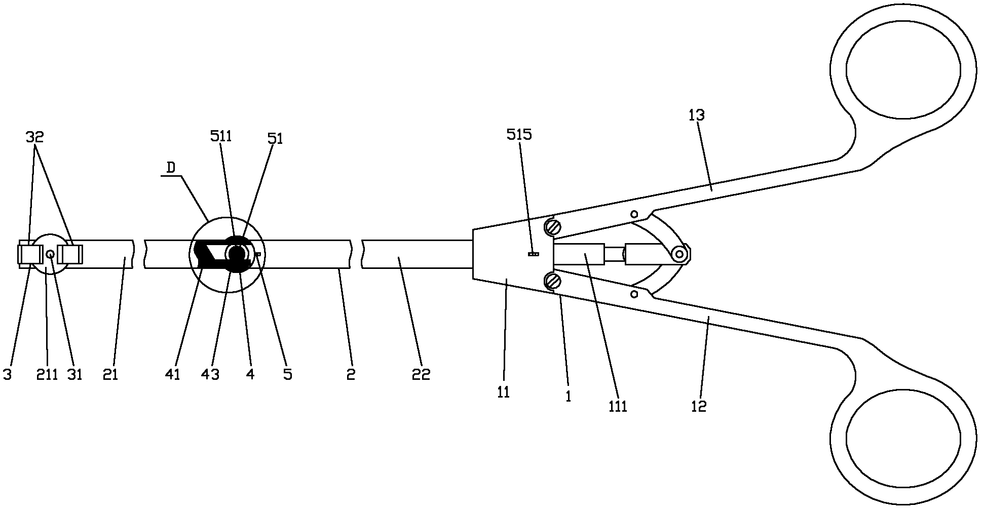
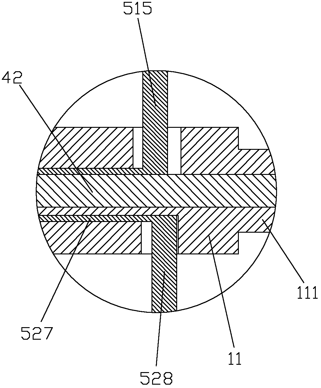
[0025] figure 1 It is the front view of the present invention, figure 2 It is a top view of the present invention, image 3 for figure 1 Partial enlarged view of A in the middle, Figure 4 for figure 1 Partial enlarged view of B in middle, Figure 5 for figure 1 Partial enlarged view at C, Figure 6 for figure 2 Partial enlarged view at middle D, as shown in the figure: the medical needle-holding forceps of this embodiment includes a pliers handle 1, a support rod 2, a pliers head 3, a transmission part 4 and a control part 5, and the support rod 2 includes a front support Rod 21 and rear strut 22, the rear end of front strut 21 is hinged at the front end of rear strut 22; Described pliers head 3 is connected to the front end of front strut 21 by rotatable movable seat 211; Said transmission part 4 Supported and positioned by the support rod 2, the rear end of the transmission part 4 is hinged to the pliers handle 1; the control part 5 is used to control the torque t...


PUM


Abstract

The invention discloses a pair of medical needle-holding forceps, comprising a forceps handle, support rods, a forceps head, a driving part and a control part, wherein the support rods comprise a front support rod and a rear support rod; the rear end of the front support rod is hinged to the front end of the rear support rod; the forceps head is connected to the front end of the front support rodthrough a rotational moving seat; the driving part is supported and positioned by the support rod; the rear end of the driving part is hinged to the forceps handle; and the control part is used for controlling the torque transmitting direction on the driving part and further realizing the swing control over the front support rod, the rotating control over the moving seat and the clamping control over the forceps head. According to the medical needle-holding forceps disclosed by the invention, the conversion of the clamping angle and the azimuth of a suture needle can be realized by using the rotation of the support rods and the forceps head of the medical needle-holding forceps; driving torque is respectively provided by clamping and kneading the forceps handle; the medical needle-holdingforceps have a reasonable structure, is convenient to use and suitable for suturing wounds at various positions and trends as well as the wounds positioned at the deep parts of human body and facilitates the improvement on the suture quality of the wounds.

Description

technical field [0001] The invention relates to a medical device, in particular to a medical needle-holding forceps which can adjust the needle-holding angle and orientation and can carry out suturing operations through the conversion process. Background technique [0002] Medical needle holders are commonly used medical instruments for surgical operations. They are used to hold medical sutures and suture wounds of patients. When medical needle holders in the prior art are used to hold medical suture needles, their clamping angle and orientation are The handle of the forceps is of a single form and cannot be adjusted. When suturing wounds with different positions and orientations, in order to achieve the required suture angle, the operator often needs to adjust the way he holds the needle forceps or even his body standing posture, which makes suturing difficult. Larger, and the medical needle-holding forceps of the prior art is only suitable for suturing the wound on the hum...

Claims


Application Information

Patent Timeline
Patent Type & Authority Applications(China)
IPC IPC(8): A61B17/06
Inventor 李宝童杨丽莎
Owner 李宝童
Why Eureka
Try Eureka