Al technical title is built by PatSnap Al team. It summarizes the technical point description of the patent document.
A punching machine, fully automatic technology, applied in metal processing and other directions, can solve the problems of large punching machine, unable to achieve automatic and precise positioning, unable to achieve automatic feeding and automatic material receiving, etc., to save rack volume and precision. high effect
Inactive Publication Date: 2011-11-23
XIAN WENXIANG INTELLIGENT TECH CO LTD
View PDF5 Cites 9 Cited by
Summary
Abstract
Description
Claims
Application Information
AI Technical Summary
This helps you quickly interpret patents by identifying the three key elements:
Problems solved by technology
Method used
Benefits of technology
Problems solved by technology
[0003] The traditional punching machine includes a frame on which the punching die is fixed, and a punch is arranged above the punching die. The working principle is that the operator puts the workpiece on the frame and aligns After the punching part, the punching is carried out. The disadvantages are: 1. Since the position of the punching die and the punch is fixed, the workpiece needs to be moved, so the punching machine is very bulky; 2. The operator needs to send the workpiece into the punching machine. Punching on the hole machine can not realize automatic feeding and automatic receiving; 3. Can not realize automatic precise positioning
Method used
Image
Click on the blue label to locate the original text in one second.
Reading with bidirectional positioning of images and text.
Examples
Embodiment Construction
[0014] The structural principle and working principle of the present invention will be further described in detail below in conjunction with the accompanying drawings.
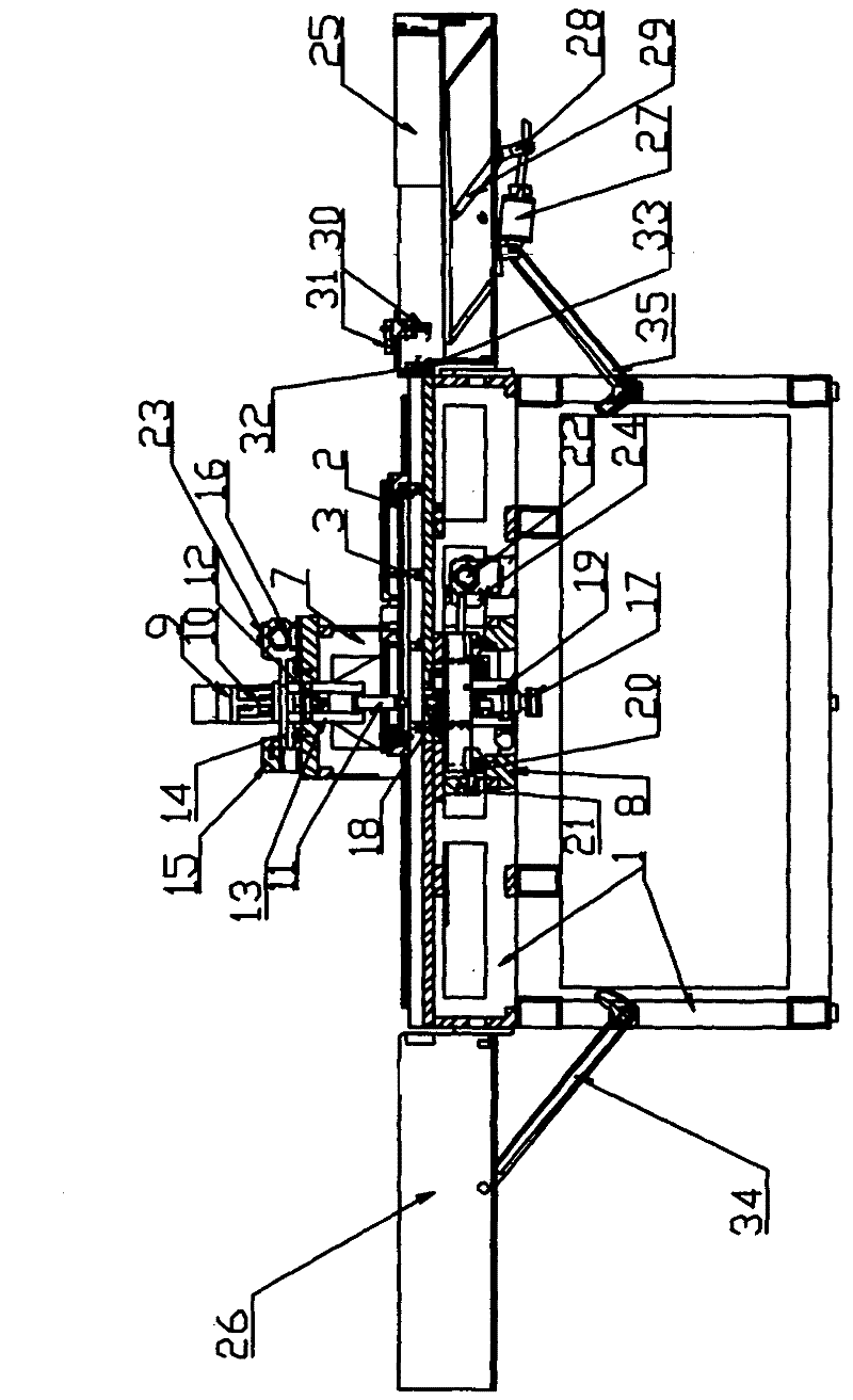
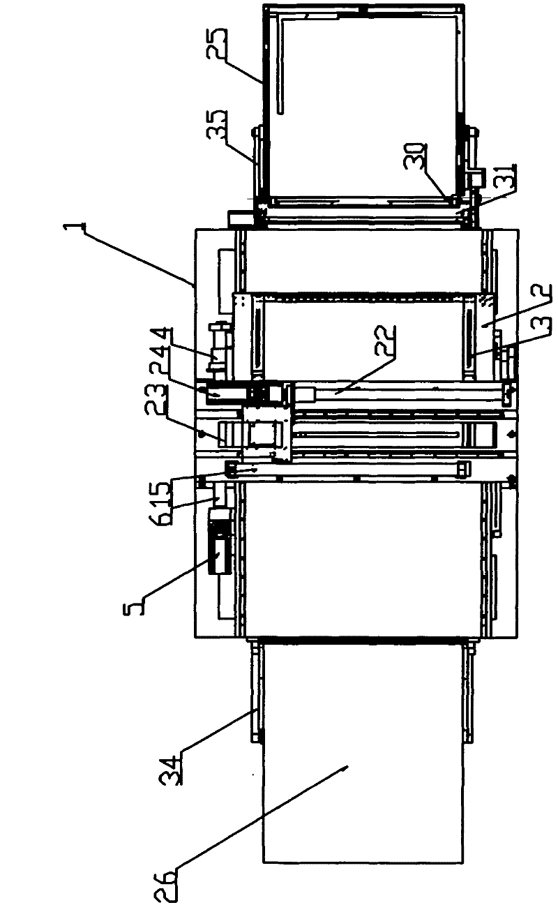
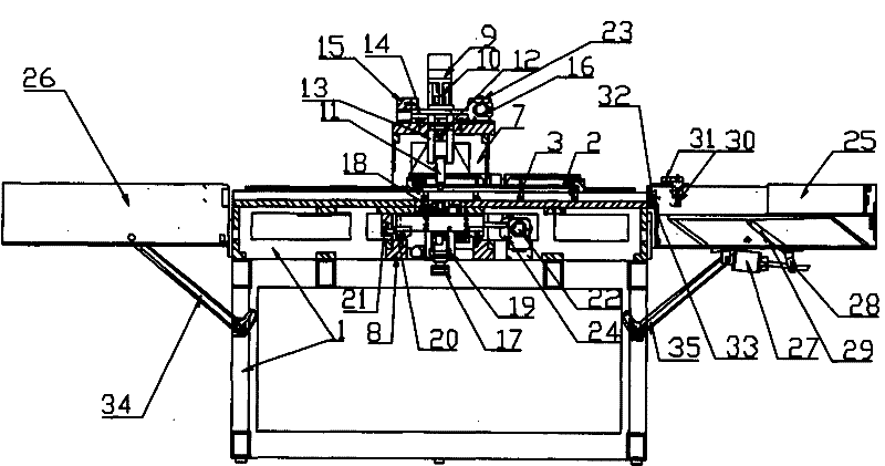
[0015] see figure 1 , 2 , a fully automatic punching machine, including a frame 1, a slidable feeding frame 2 is provided on the frame 1, a vacuum suction cup 3 is provided on the feeding frame 2, and the position of the vacuum suction cup 3 on the feeding frame 2 can be adjusted according to the processing The width of the piece is properly adjusted. One side of the feeding frame 2 is provided with a sliding sleeve 4, which is matched with the screw 6 on the motor 5. An upper punching frame 7 and The lower punch frame 8 and the upper punch frame 7 are provided with a cylinder 9, the cylinder connecting rod 10 is provided with an upper punch 11, one side of the upper punch 11 is provided with a camera 12, and one side of the shell 13 of the upper punch 11 A positioning rod 14 is provided, and the positioning...
PUM
Abstract
The invention provides a full-automatic punching machine. In the machine, a vacuum suction cup is arranged on a feed stand of a frame; a sliding bush is arranged on one side of the feed stand, and matched with a screw on a motor 1; an upper punching rack and a lower punching rack are arranged above and below the feed stand respectively; a cylinder is arranged on the upper punching rack; an upper punch is arranged on the connecting rod of the cylinder; a positioning rod 1 is arranged on the upper punch and in sliding connection with a grating scale of an upper die; the other side of a shell 1 is matched with a screw of the upper die; the lower punching rack is provided with a lifting device of a lower die; a lower punch is arranged at the upper part of the lifting device of the lower die; a positioning rod 2 is arranged on one side of the lifting device of the lower die, and connected with a grating scale of the lower die; the other side of the shell 2 is connected with the screw of the lower die; the frame is provided with an automatic feeding tank and a discharging tank; after the automatic discharging tank feeds a processing piece into the frame, the processing piece is delivered between the upper punch and the lower punch for punching along a Y direction under driving of the feed stand; and the punched processing piece is fed into a collecting tank. The full-automatic punching machine has the characteristics of small volume, automatic feeding and collecting and accurately positioned punching.
Description
technical field [0001] The invention belongs to the technical field of punching machines, and in particular relates to a fully automatic punching machine. Background technique [0002] Small hole punching machine is suitable for punching leather, cowhide, artificial leather, plastic, PU, EVA, PVC, various cloth, paper, leather accessories, shoe uppers, decorative pieces, curtains, car leather chairs, etc. In the field of processing, it is widely used in circuit board manufacturing, auto parts (breathable cushion), luggage and handbags, stationery, shoes, breathable materials, advertising paper products and other industries. [0003] The traditional punching machine includes a frame on which the punching die is fixed, and a punch is arranged above the punching die. The working principle is that the operator puts the workpiece on the frame and aligns After the punching part, the punching is carried out. The disadvantages are: 1. Since the position of the punching die and th...
Claims
Application Information
Patent Timeline
Application Date:The date an application was filed.
Publication Date:The date a patent or application was officially published.
First Publication Date:The earliest publication date of a patent with the same application number.
Issue Date:Publication date of the patent grant document.
PCT Entry Date:The Entry date of PCT National Phase.
Estimated Expiry Date:The statutory expiry date of a patent right according to the Patent Law, and it is the longest term of protection that the patent right can achieve without the termination of the patent right due to other reasons(Term extension factor has been taken into account ).
Invalid Date:Actual expiry date is based on effective date or publication date of legal transaction data of invalid patent.