Cloth tension control device

A technology of tension control and cloth, which is applied in the direction of thin material handling, transportation and packaging, winding strips, etc., can solve the problems of speed out of sync, quality problems, etc., and achieve the effect of improving process efficiency

Inactive Publication Date: 2011-11-23
JIANGSU SHENGFANG NANO MATERIAL TECH CO LTD
View PDF10 Cites 3 Cited by
  • Summary
  • Abstract
  • Description
  • Claims
  • Application Information

AI Technical Summary

Problems solved by technology

like figure 1 As shown, in the cloth take-up device, the cloth is rolled onto the storage roller 2 after passing around the first roller 1. In this process, since the first roller 1 and the storage roller 2 have different rotational speeds, the first The speed of the fabric passing on roller 1 is not synchronized with the speed of the fabric received on the take-up roller 2, causing quality problems

Method used


Image

  • Cloth tension control device
  • Cloth tension control device
  • Cloth tension control device

Examples


Embodiment Construction

[0010] The technical solution of the present invention will be described in detail below in conjunction with the accompanying drawings.

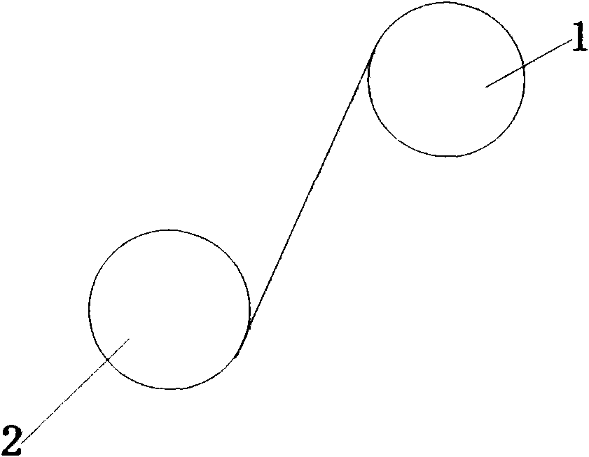
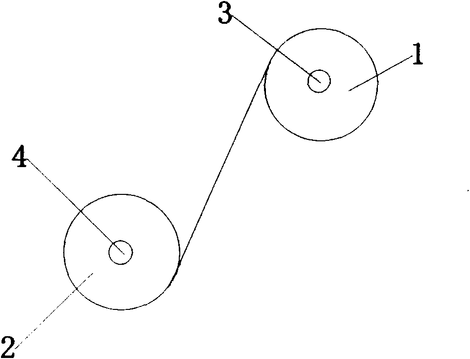
[0011] figure 2 A schematic diagram of installation of the cloth tension control device described in the present invention is shown. like figure 2 As shown, in the cloth take-up device, the cloth to be wound up is rolled onto the second roller 2 after passing around the first roller 1, and the first roller 1 and the second roller 2 are driven by the first driving unit and the second roller respectively. The second drive unit is pivotally driven.

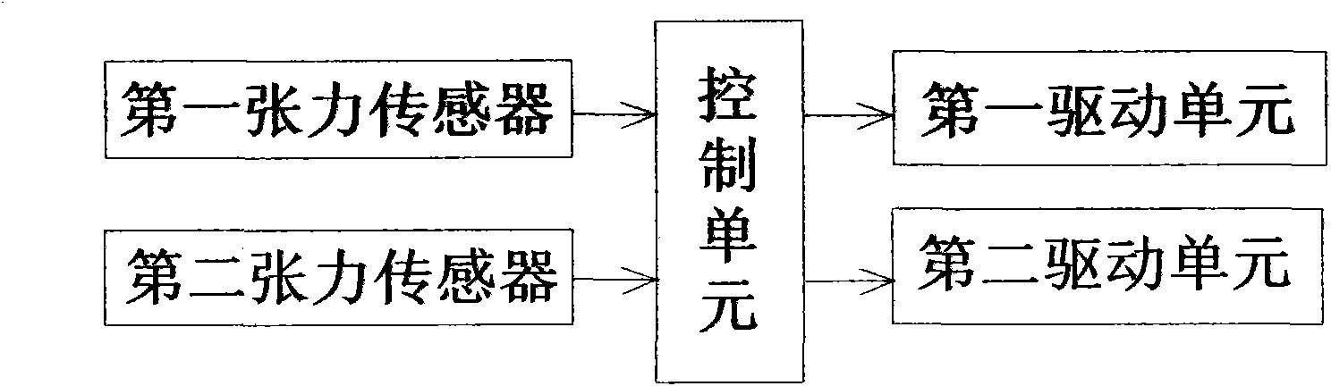
[0012] Figure 2-3 As shown, the cloth tension control device includes a control unit, and a first tension sensor 3 and a second tension sensor 4 electrically connected to the control unit; wherein, the control unit is used to drive the first and second tension sensors The rollers rotate at a predetermined speed, so as to achieve the purpose of adjusting the tension of the fabric; the first t...


PUM


Abstract

The invention relates to a cloth tension control device. Cloth to be reeled bypasses a first roller and then is collected to a second roller. The cloth tension control device is characterized by comprising a control unit, a first tension sensor, a second tension sensor, a first driving unit and a second driving unit, wherein the first tension sensor and the second tension sensor are electrically connected with the control unit and are arranged on the first and second rollers respectively; the first and second driving units are used for driving the first roller and the second roller respectively; and the control unit is electrically connected with the first and second driving unit. In the tension control device, the first and second tension sensors are used for acquiring tension on the two rollers of a cloth collection device and transmitting the tension to the control unit, and the control unit is used for adjusting the rotating speed of a corresponding roller according to the magnitude of the tension on the two rollers, so that the cloth to be reeled keeps appropriate tension; therefore, process efficiency and the quality of finished cloth are improved.

Description

technical field [0001] The invention relates to a tension control device, in particular to a cloth tension control device. Background technique [0002] figure 1 A schematic structural view of a cloth collecting device in the prior art is shown. like figure 1 As shown, in the cloth take-up device, the cloth is rolled onto the storage roller 2 after passing around the first roller 1. In this process, since the first roller 1 and the storage roller 2 have different rotational speeds, the first The speed of the cloth passing on the roller 1 is not synchronized with the speed of the cloth received on the take-up roller 2, causing quality problems. In the prior art, the technical process is to judge the quality of the finished cloth by the experience of engineers and testing tools. Contents of the invention [0003] The object of the present invention is to provide a cloth tension control device with simple structure, reliable performance and low cost, which is used to impr...

Claims


Application Information

Patent Timeline
Patent Type & Authority Applications(China)
IPC IPC(8): B65H23/195B65H26/04
Inventor 朱云斌
Owner JIANGSU SHENGFANG NANO MATERIAL TECH CO LTD
Why Eureka
Try Eureka