Supercharge Your Innovation With Domain-Expert AI Agents!

Driving mechanism of dual-motor clutch of electronic lock

A driving mechanism and dual-motor technology, which is applied in building locks, building structures, and non-mechanical transmission-operated locks, etc., can solve the problems of poor opening performance of mechanical lock resistance technology and restrict the market application of electronic locks, and achieve simple structure, Increased extra wear, reliable operation

Inactive Publication Date: 2013-05-29
SHANGHAI MYTEC DIGITAL
View PDF6 Cites 0 Cited by
  • Summary
  • Abstract
  • Description
  • Claims
  • Application Information

AI Technical Summary

Problems solved by technology

[0002] At present, all electronic locks use a single-motor clutch drive mechanism. Due to the reliability problems of the electronic control module and the motor execution module, the existing electronic locks still retain the mechanical lock part as a backup. The mechanical lock resistance technology has poor opening performance. The part of the mechanical lock reserved on the lock has become the bottleneck of the security of the entire electronic lock
The electronic control module of the electronic lock is technically feasible to achieve double backup. Due to the constraints of the battery power supply capacity, space, cost, complexity and other factors of the electronic lock, the motor execution module has not appeared a dual-motor clutch drive mechanism to perform backup. This seriously restricts the market application of electronic locks

Method used


Image

  • Driving mechanism of dual-motor clutch of electronic lock
  • Driving mechanism of dual-motor clutch of electronic lock
  • Driving mechanism of dual-motor clutch of electronic lock

Examples


Embodiment Construction

[0025] The present invention will be further described below in conjunction with the accompanying drawings and embodiments.

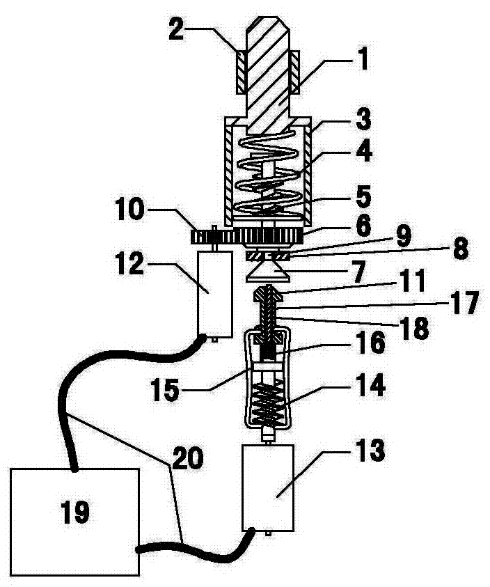
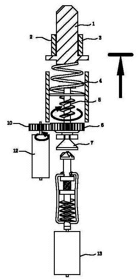
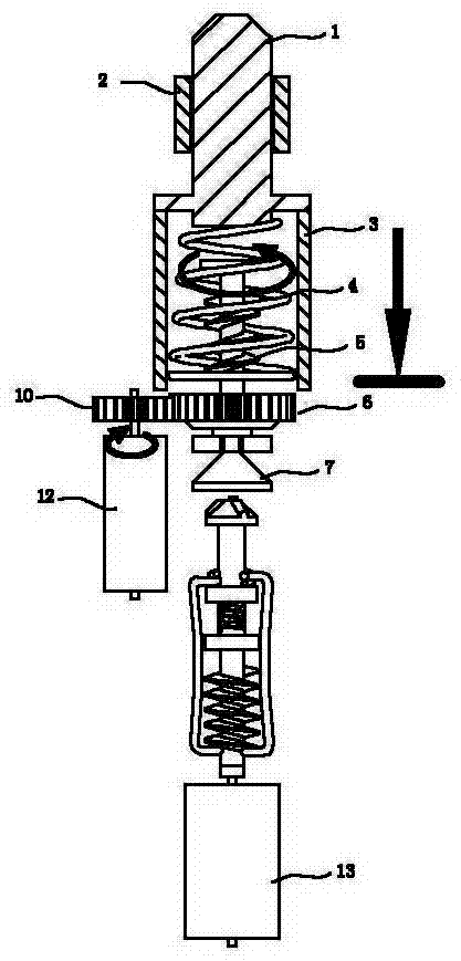
[0026] figure 1 It is a structural schematic diagram of the dual-motor clutch driving mechanism of the electronic lock of the present invention.

[0027] See figure 1 , the electronic lock dual-motor clutch drive mechanism provided by the present invention includes a drive pin 1, a guide sleeve 2, a limit stop frame 3, a drive spring 4, a drive worm 5, a first driven gear 6, a second driven Moving gear 7, bracket 8, connecting shaft 9, first driving gear 10, second driving gear 11, main motor 12, auxiliary motor 13, clutch worm 14, clutch connecting rod 15, compression spring 16, the cross section of the upper section is D A font-shaped auxiliary motor output shaft 17, a second driving gear annular chute 18, an electronic control module 19, and a transmission line 20. The first driving gear 10 is contained in the upper section of the output shaft of ...


PUM


Abstract

The invention discloses a driving mechanism of a dual-motor clutch of an electronic lock, and the driving mechanism comprises a driving pin, a main motor, a first driving gear and a first driven gear, which are arranged in a housing, wherein the first driven gear is connected with the driving pin through a transmission mechanism, and the first driving gear is meshed and connected with the first driven gear; and the driving mechanism of the dual-motor clutch of the electronic lock further comprises an auxiliary motor, wherein the first driven gear is connected with a second driven gear througha connecting shaft, the auxiliary motor is meshed and connected with the second driven gear through a clutch mechanism, and a shaft of the auxiliary motor and the connecting shaft are positioned on the same straight line. The driving mechanism of the dual-motor clutch of the electronic lock provided by the invention is characterized in that the auxiliary motor is arranged and the auxiliary motor is connected with the first driven gear through the clutch mechanism, the second driven gear and the connecting shaft, therefore complete redundancy backup of the electronic lock is realized. The driving mechanism is simple in structure, reliable to operate and further avoids increasing additional loss of electrical energy.

Description

technical field [0001] The invention relates to an electronic lock driving mechanism, in particular to an electronic lock dual-motor clutch driving mechanism. Background technique [0002] At present, electronic locks use a single-motor clutch drive mechanism. Due to the reliability problems of the electronic control module and the motor execution module, the existing electronic locks still retain the mechanical lock part as a backup. The mechanical lock resistance technology has poor opening performance. The part of the mechanical lock reserved on the lock has become the bottleneck of the security of the entire electronic lock. The electronic control module of the electronic lock is technically feasible to achieve dual backup. Due to the constraints of the battery power supply capacity, space, cost, and complexity of the electronic lock, the motor execution module has not yet appeared a dual-motor clutch drive mechanism to perform backup. This seriously restricts the marke...

Claims


Application Information

Patent Timeline
Patent Type & Authority Patents(China)
IPC IPC(8): E05B47/00E05B15/00
Inventor 詹万泉黄立严
Owner SHANGHAI MYTEC DIGITAL
Features
  • R&D
  • Intellectual Property
  • Life Sciences
  • Materials
  • Tech Scout
  • Unparalleled Data Quality
  • Higher Quality Content
  • 60% Fewer Hallucinations
Learn More