Novel pipeline type flow deflector oil-water separator rotation starting device

An oil-water separator and deflector technology, which is applied in the fields of production fluids, wellbore/well components, earth-moving drilling, etc., can solve the problems of complicated equipment and troublesome maintenance, avoid oil-water remixing, and improve the swirl field. The effect of improving separation efficiency

Inactive Publication Date: 2011-11-23
INST OF MECHANICS - CHINESE ACAD OF SCI
View PDF9 Cites 16 Cited by
  • Summary
  • Abstract
  • Description
  • Claims
  • Application Information

AI Technical Summary

Problems solved by technology

However, in the underground, the use of dynamic deflectors to spin also has disadvantages, which makes the equipment complicated and maintenance troublesome

Method used


Image

  • Novel pipeline type flow deflector oil-water separator rotation starting device
  • Novel pipeline type flow deflector oil-water separator rotation starting device
  • Novel pipeline type flow deflector oil-water separator rotation starting device

Examples


Embodiment Construction

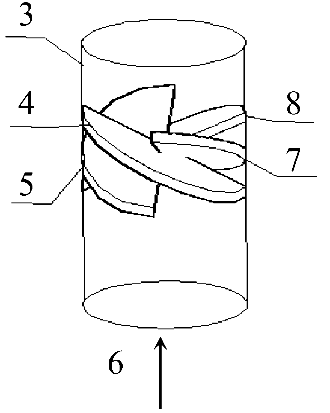
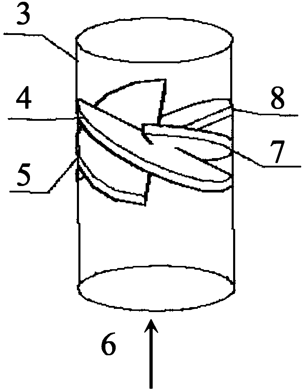
[0018] Such as figure 1 As shown, the spinning device of the present invention includes: 4 guide vanes 4, 5, 7, 8 that can be fixedly and obliquely installed in the pipeline 3, and the guide vanes 4, 5, 7, 8 are evenly distributed along the circumference of the pipeline 3, And in the axial direction of the pipeline 3 are stacked successively. When the fluid mixed with oil and water flows through the deflectors 4, 5, 7, and 8 along the flow direction 6, a center-symmetrical swirl field will be formed, in which the oil and water are separated due to different centrifugal forces due to different densities. .

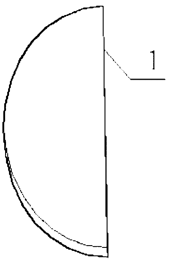
[0019] Such as figure 2 As shown, the deflectors 4, 5, 7, and 8 are made of semi-elliptical stainless steel or other wear-resistant materials, and the angle θ between the long axis of the deflectors 4, 5, 7, and the cross-section of the pipe 3 is is 45°, the short axis is parallel to the cross section of the pipe 3, that is, the angle α between the short axis and the cr...


PUM


Abstract

The invention discloses a novel pipeline type flow deflector oil-water separator rotation starting device, and the device provided by the invention comprises more than two flow deflectors capable of being fixedly and obliquely mounted in a pipeline, wherein the flow deflectors are uniformly distributed along the circumferential direction of the pipeline and sequentially superposed in the axial direction of the pipeline; and when an oil and water mixed fluid flows by the flow deflectors, a swirling flow field in central symmetry is formed, thus oil and water are further centrifugally separated. The novel rotation-starting device has the following effects: when the oil and the water enter into the rotation-starting device equipped with the oil-water separator in a certain proportion, the oil and the water meet the flow deflectors, as the flow deflectors are circumferentially oblique in the same direction, the flow of the part of the fluid under flow deflection of each flow deflector along the annular direction is bascially same, thus a consistent vortex effect can be achieved and the stronger vortex can be formed; and simultaneously, the flow deflectors which are mounted axially can be used for reducing the radial motion distance of oil drops and enabling the oil drops to move to an axle center faster. Therefore, the better oil-water separation effect can be played.

Description

technical field [0001] The invention relates to a device for swirling to form a swirling flow field in a novel oil-water cyclone separator, in particular to an oil-water separator swirling device used in an oil-water separation system downhole. Background technique [0002] With the prolongation of oilfield development time, water production continues to increase, which increases production costs. In order to reduce production costs, it has become a consensus to use downhole oil-water separators to separate water and reinject it into formations in situ. [0003] The separation principles currently used for downhole oil-water separation are mainly gravity and centrifugation. For example, the patent publication number: CN 101025080A, the method of multi-cup isoflow downhole oil-water separator to realize injection and production of high water-cut wells in the same well uses the principle of gravity. Oil and water are separated by natural sedimentation. Publication number: CN2...

Claims


Application Information

Patent Timeline
Patent Type & Authority Applications(China)
IPC IPC(8): E21B43/40
Inventor 吴应湘史仕荧许晶禹张军郭军王淑京
Owner INST OF MECHANICS - CHINESE ACAD OF SCI
Why Eureka
Try Eureka