Lens, LED (light emitting diode) light source device and LED (light emitting diode) backlight module

A technology of LED light sources and lenses, applied in the field of LED applications, can solve the problems of increased power consumption, unfavorable driving, and impact of LED backlight modules

Inactive Publication Date: 2011-11-23
HISENSE VISUAL TECH CO LTD
View PDF12 Cites 20 Cited by
  • Summary
  • Abstract
  • Description
  • Claims
  • Application Information

AI Technical Summary

Problems solved by technology

However, this also leads to an increase in the density of LEDs in the backplane, which greatly increases the power cons...

Method used


Image

  • Lens, LED (light emitting diode) light source device and LED (light emitting diode) backlight module
  • Lens, LED (light emitting diode) light source device and LED (light emitting diode) backlight module
  • Lens, LED (light emitting diode) light source device and LED (light emitting diode) backlight module

Examples


Embodiment Construction

[0020] In order to understand the above-mentioned purpose, features and advantages of the present invention more clearly, the present invention will be further described in detail below in conjunction with the accompanying drawings and specific embodiments.

[0021] In the following description, many specific details are set forth in order to fully understand the present invention, but the present invention can also be implemented in other ways different from those described here, therefore, the present invention is not limited to the specific embodiments disclosed below limit.

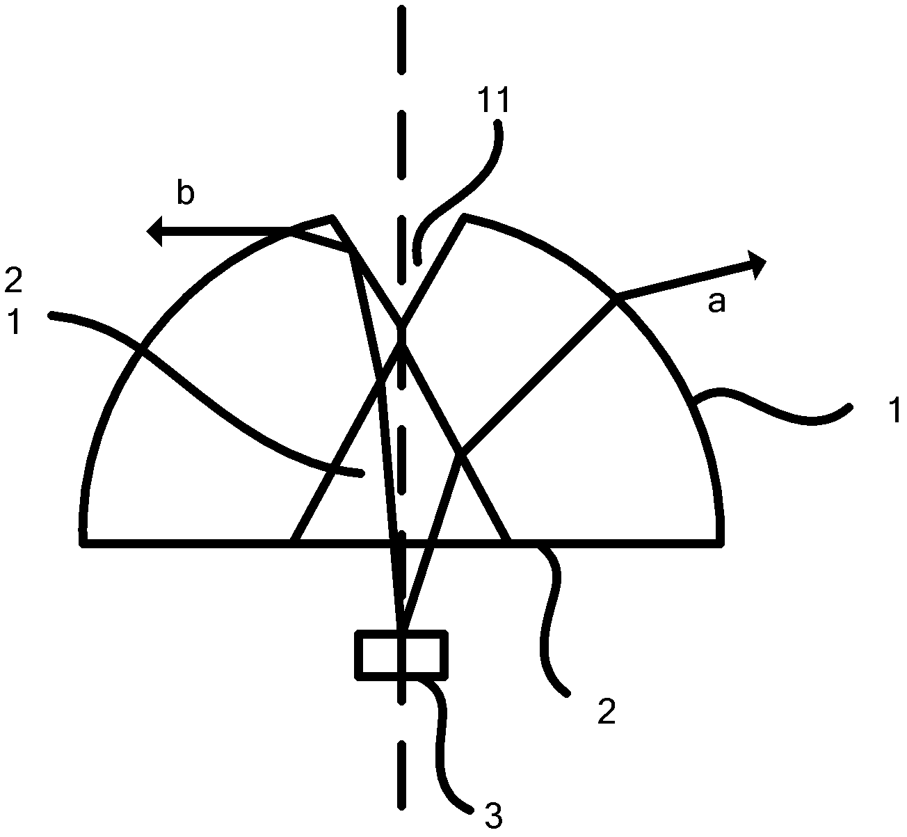
[0022] figure 1 is a schematic diagram of a lens according to one embodiment of the present invention.

[0023] Such as figure 1 As shown, the present invention provides a lens, which is assembled in an LED light source device, and is characterized in that the lens has an upper surface 1 and a bottom surface 2, and the bottom surface 1 is provided with a first concave portion 21, and the first conca...


PUM


Abstract

The invention provides a lens which can be assembled in an LED (light emitting diode) light source device and is provided with an upper surface and a bottom surface, wherein a first concave part is arranged on the bottom surface, the first concave part is provided with a same central axis with the lens, and the bottom of the first concave part is positioned on the bottom surface. The invention also provides an LED light source device and an LED backlight module. According to the technical scheme of the invention and the secondary optical design of the lens, the light utilization rate is increased, the number of LEDs is reduced, the power dissipation of the LED backlight module is reduced, and the direct type backlight mixing distance is reduced, and a backlight ultrathin design is achieved.

Description

technical field [0001] The invention relates to the field of LED applications, in particular to a lens, an LED light source device and an LED backlight module. Background technique [0002] For the current liquid crystal screen manufacturing process, most of the LED (light emitting diode) light-emitting lenses in the direct-lit backlight module belong to the primary optical design. This usually creates the following problems. Due to the limitation of the lens design space, its radiation angle is generally 120 degrees Lambertian distribution, and the thickness of the backlight module is also subject to the influence of the LED light angle. Under a certain power consumption, the backlight module must have a certain thickness. Realize light mixing and ensure that the LED beam spreads evenly. Therefore, it is difficult to achieve ultra-thin LCD screens with current LED lenses. [0003] In order to achieve ultra-thin backlight modules for screens, most of the industry currently...

Claims


Application Information

Patent Timeline
IPC IPC(8): F21V5/04F21S8/00F21Y101/02
Inventor 张志睿乔明胜钟强高上
Owner HISENSE VISUAL TECH CO LTD
Why Eureka
Try Eureka