
Zoom laser illuminator

A technology of illuminator and laser, which is applied to zoom laser illuminator. field, to achieve the effect of ingenious design, cost reduction and large zoom ratio

Active Publication Date: 2012-09-05
山东神戎电子股份有限公司
View PDF1 Cites 0 Cited by
  • Summary
  • Abstract
  • Description
  • Claims
  • Application Information

AI Technical Summary

Problems solved by technology

[0003] In order to solve the existing problems in the prior art, the present invention provides a technical solution of a zoom laser illuminator with a large zoom magnification and uniform illumination spot, which realizes illumination by the principle of imaging

Method used


Image

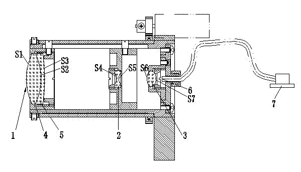
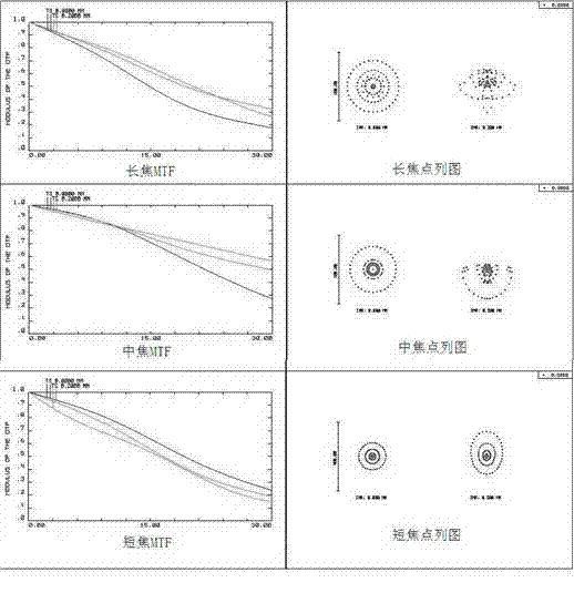
  • Zoom laser illuminator
  • Zoom laser illuminator
  • Zoom laser illuminator

Examples


Embodiment Construction

[0018] In order to clearly illustrate the technical characteristics of this program, a specific implementation will be adopted below, combined with its

[0019] Accompanying drawing, this scheme is described.

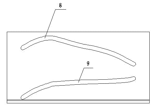
[0020] As shown in the accompanying drawings, the present invention is a zoom laser illuminator. Along the optical axis direction to the light-emitting end face of the laser, there are sequentially arranged: a first lens with positive refractive power, a second lens with negative refractive power, and a third lens with positive refractive power. The first lens can be away from the light-emitting end face of the laser and then close to the end face of the laser, the second lens always moves toward the light-emitting end face of the laser, and the third lens is fixed.

[0021] The zoom ratio of the zoom laser illuminator is F2 / F1≥40, and F1≤2mm, where F1 is the effective focal length at the short focal end of the zoom laser illuminator, F2 is the effective focal length at...


PUM


Abstract

The invention discloses a zoom laser illuminator. The invention adopts the technical scheme that: in the zoom laser illuminator, a first lens with positive refractive power, a second lens with negative refractive power and a third lens with the positive refractive power are sequentially arranged from the direction of an optical shaft to the direction of a luminous end face of a laser; the first lens can be away from the luminous end face of the laser firstly and then be close to an end face of the laser; the second lens always moves to the direction of the luminous end face of the laser; and the third lens is stable. The invention has the advantages that: the zoom laser illuminator is simple in structure and smart in design; the zoom laser illuminator adopts an architecture which consistsof the first lens with the positive refractive power, the second lens with the negative refractive power and the third lens with the positive refractive power; and the zoom laser illuminator consistsof three lenses, and 40-time focal distance change is realized by moving two lenses, so the high-penetration rate and easiness for assembly of the zoom laser illuminator are guaranteed, and cost is reduced.

Description

technical field [0001] The invention is a zoom laser illuminator. Background technique [0002] Most of the existing laser illuminators use single or two lenses to achieve illumination. The focal length of this illumination system remains unchanged or changes very little, and the change of illumination angle is realized by defocusing. The illuminator of this method only has a very uniform illumination spot at a certain angle, and the illumination spot at other angles is uneven, such as utility model 200620084576. In addition, the maximum illumination angle of the illuminator is limited by the divergence angle of the fiber laser. Contents of the invention [0003] In order to solve the existing problems in the prior art, the present invention provides a technical proposal of a zoom laser illuminator with large zoom magnification and uniform illumination spot, which realizes illumination by the principle of imaging. [0004] The present invention is achieved through the fo...

Claims


Application Information

Patent Timeline
Patent Type & Authority Patents(China)
IPC IPC(8): G02B15/173
Inventor 郭长林付效奎张龙年陶小凯张超岳
Owner 山东神戎电子股份有限公司
Learn More