Microchannel heat exchanger and manufacturing method thereof

A micro-channel heat exchanger and intermediate channel technology, which is applied in the field of micro-channel heat exchangers and their production, can solve the problem of aggravating the instability of a single-arm suspension structure, unbalanced flow of heat exchange working medium, and stress on a distribution pipe 9 Unevenness and other problems, to achieve the effect of simple and reasonable structure, low production cost and uniform distribution

Active Publication Date: 2011-11-23
GD MIDEA AIR-CONDITIONING EQUIP CO LTD
View PDF7 Cites 4 Cited by
  • Summary
  • Abstract
  • Description
  • Claims
  • Application Information

AI Technical Summary

Problems solved by technology

[0004] see figure 1 , the existing microchannel heat exchanger includes a header 1, a flat tube 2, a fin 3, a first end plate 4, a distribution pipe 9, a second end plate 10, etc. It can be seen that the distribution pipe 9 starts from the second end The positioning hole 11 in the plate 10 passes through and is welded together with it. The distribution pipe 9 is provided with a plurality of distribution holes 8. The first port 5 of the distribution pipe 9 is open and not fixedly connected, forming a single arm The suspension structure has a tendency to sag due to the influence of the gravity of the distribution pipe 9 itself. At the same time, the flow rate of the heat exchange medium is relatively fast, and the heat exchange medium mixed with gas and liquid makes the force on the distribution pipe 9 uneven, which is more serious. Eliminates the instability of the single-arm suspension structure, which is prone to vibration and noise
Since the first port 5 of the distribution pipe 9 is open, and when the heat exchange working medium enters the distribution pipe 9, a relatively large flow rate will be formed at the first port 5 of the distribution pipe 9, causing the heat exchange working medium there to The flow rate of the heat exchange medium is greater than that of the heat exchange medium flowing out from the distribution hole 8, resulting in an unbalanced flow of the heat exchange medium

Method used


Image

  • Microchannel heat exchanger and manufacturing method thereof
  • Microchannel heat exchanger and manufacturing method thereof
  • Microchannel heat exchanger and manufacturing method thereof

Examples


Embodiment 1

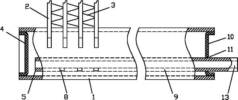
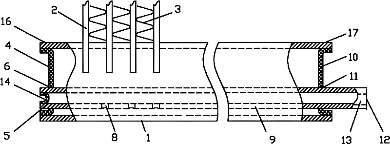
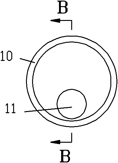
[0036] see Figure 2-Figure 4 , figure 2 The microchannel heat exchanger in it includes a header 1, a flat tube 2, fins 3, a first end plate 4, a distribution pipe 9, a second end plate 10, a distribution hole 8 arranged on the distribution pipe 9, and a The assembly hole 6 on the first end plate 4, the inlet 12 on the distribution pipe 9, the first port 5 of the distribution pipe 9, the second port 13 of the distribution pipe 9, and the positioning hole 11 arranged on the second end plate 10 , the first end 16 of the header 1 , and the second end 17 of the header 1 .

[0037] The flat tube 2 is provided with an intermediate channel, the fins 3 are arranged between the flat tubes 2, the distribution pipe 9 is provided in the collecting pipe 1, and the side wall of the distribution pipe 9 is provided with an inner cavity that can lead to the collecting pipe 1 The dispensing hole 8.

[0038] The first port 5 of the distribution pipe 9 passes through the assembly hole 6 on th...

Embodiment 2

[0059] Embodiment 2 of the present invention differs from Embodiment 1 in that, as Figure 5-Figure 6 As shown, the header 1 of the second embodiment is also provided with an internal bracket 7 for supporting the distribution pipe 9, such as Image 6 As shown, the upper part of the inner bracket 7 is curved, and the lower part is connected to the header 1. In this embodiment, the inner bracket 7 and the tube wall of the header 1 are fixed by welding. In this way, the inner bracket 7 can support the distribution pipe 9, further reducing the vibration of the distribution pipe 9. Brazing material can also be applied between the internal bracket 7 and the distribution pipe 9, and then through integral welding, the two can be connected and fixed together more stably, and the effect of reducing vibration and noise is better.

[0060] Another benefit of adopting the inner bracket 7 is that in the manufacturing step d, when the distribution pipe stretches forward, the inner bracket 7...

Embodiment 3

[0063] Embodiment 3 of the present invention differs from Embodiment 2 in that, as Figure 7 As shown, the positioning protrusion 27 in the collector 7 of the third embodiment is not connected to the collector by welding, but formed in the collector by mechanical extrusion. Likewise, the positioning protrusion 27 can support the distribution pipe 9 to reduce vibration. The advantage of using the positioning protrusion 27 in the third embodiment is that it can be processed and formed before heating and brazing. In manufacturing step d, the distribution tube is pressed against the positioning protrusion 27, because the positioning protrusion 27 is integral with the header and does not affect its quality. However, in the second embodiment, before heating and brazing, the internal bracket 7 has not been melted and fixed with the collector. Of course, in this embodiment, the positioning protrusion 27 also has the positioning function as in the second embodiment.

[0064] See emb...


PUM


Abstract

The invention discloses a microchannel heat exchanger and a manufacturing method thereof. The microchannel heat exchanger comprises a plurality of flat pipes which are communicated with a flow collection pipe; a middle passage is formed in each flat pipe; fins are arranged between flat pipes; a distribution pipe is arranged in the flow collection pipe; the side wall of the distribution pipe is provided with distribution holes which are communicated with the inner cavity of the flow collection pipe; a first end of the flow collection pipe is provided with a first end plate which is provided with an assembly hole; a first end port of the distribution pipe passes through the assembly hole; the first end port and the assembly hole are fixed and sealed through welding; the first end port of the distribution pipe is plugged through a plug or a cover; the first end port is fixed and sealed with the plug or the cover through welding; the external diameter of the distribution pipe which is inserted into the assembly hole is a fixed value; and the aperture of the assembly hole is a fixed value. The manufacturing method can greatly improve the processing efficiency of the microchannel heat exchanger, and the microchannel heat exchanger has the characteristics of simple and reasonable structure, low manufacturing cost and the like, and can be operated flexibly and distribute flow uniformly, stably and reliably.

Description

technical field [0001] The invention relates to a heat exchanger, in particular to a microchannel heat exchanger and a manufacturing method thereof. Background technique [0002] As a new type of heat exchanger, microchannel heat exchanger has been widely concerned and applied. [0003] In order to improve the uniform fluidity of the heat exchange working medium in the microchannel heat exchanger, the structure of inserting the distribution pipe into the header of the microchannel heat exchanger is often adopted, and the heat exchange working medium is divided through the holes on the distribution pipe. Improve the uniformity of the heat exchange working medium entering the flat tube in the microchannel heat exchanger. [0004] see figure 1 , the existing microchannel heat exchanger includes a header 1, a flat tube 2, a fin 3, a first end plate 4, a distribution pipe 9, a second end plate 10, etc. It can be seen that the distribution pipe 9 starts from the second end The ...

Claims


Application Information

Patent Timeline
Patent Type & Authority Applications(China)
IPC IPC(8): F28F9/26
CPCF28F9/0273
Inventor 刘阳李强佐藤宪一郎
Owner GD MIDEA AIR-CONDITIONING EQUIP CO LTD
Why Eureka
Try Eureka