
Midsize direct shear apparatus with non-lever type loading

A direct shear instrument and lever-type technology, which is used in the field of devices for testing the shear strength, stress and strain behavior of soil, the shear strength of soil and soil-rock mixtures, and the devices for testing crushed stone and residual shear strength. Reduced shear area, increased normal stress, uneven stress, etc.

Inactive Publication Date: 2011-11-23
DALIAN UNIV OF TECH
View PDF7 Cites 14 Cited by
  • Summary
  • Abstract
  • Description
  • Claims
  • Application Information

AI Technical Summary

Problems solved by technology

[0005] In order to overcome the deficiency that the shear area of ​​the existing direct shear instrument gradually decreases with the occurrence of the shear displacement during the test process, causing the normal stress to gradually increase with the decrease of the shear area, the problem to be solved by the present invention The technical problem is to provide a medium-sized direct shear apparatus in which the vertical normal stress remains constant during the test
Secondly, in order to solve the deficiencies and defects of traditional vertical lever loading, the present invention provides a vertical servo motor-driven loading scheme. In addition, in order to solve the problem of structural deformation during horizontal loading, the present invention provides a belt Diagonal bracing frame structure scheme
Successfully solved the stability problem of the structure under horizontal loading
In order to overcome the problem of uneven stress caused by rollers supporting the shear box, the invention provides a support device with uniform stress

Method used


Image

  • Midsize direct shear apparatus with non-lever type loading
  • Midsize direct shear apparatus with non-lever type loading
  • Midsize direct shear apparatus with non-lever type loading

Examples


Embodiment Construction

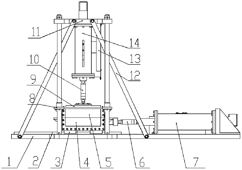
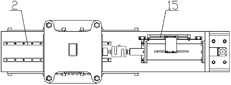
[0013] The present invention will be further described below in conjunction with the accompanying drawings and embodiments.

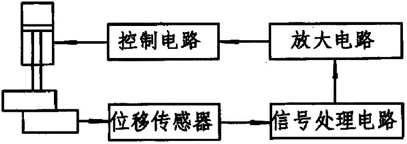
[0014] Such as figure 1 , figure 2 , image 3 As shown, the medium-sized direct shear instrument of the present invention includes base plate 1, double track 2, lower shear box 4, loading plate 9, horizontal loading device 7 and vertical loading device 14, vertical loading device supports 11, and the upper direct shear box is fixed device 8. The displacement of the lower shearing box is measured by the grating ruler 15 installed on the horizontal loading device, and the reduction value of the shearing area is calculated, which is used to control the loading force of the vertical loading device and realize the dynamic constant of the directional stress.

[0015] The displacement signal measured by the grating ruler is processed by the signal and amplified by the amplifying circuit, and then sent to the control circuit of the vertical loading device 7...


PUM


Abstract

The invention discloses a midsize direct shear apparatus with non-lever type loading, comprising dual rails, a base, a lower shear box, an upper shear box, a pressure transferring plate, a horizontal loading device and a vertical loading device mounted on a beam, wherein the horizontal and vertical loading devices are respectively realized by the way of a stepping motor and a lead screw. Both the load applied to the vertical direction and the load applied to the horizontal direction are measured by a load sensor. The vertical displacement and the horizontal displacement are measured and further controlled by a grating ruler displacement sensor fixed on the lead screw. The shearing area reducing value can be indirectly obtained through the measured value of the vertical displacement and the horizontal displacement, so as to control the loading force of the vertical loading device, that is to say the vertical normal stress can keep a dynamic constant. The direct shear test can more realistically reflect the actual shear strength characteristics of the rock and the soil. Due to the adoption of a transparent toughened glass mode and a matched digital camera, the development change process of the shear surface can be tracked and observed in a real-time manner.

Description

technical field [0001] The invention relates to a device for testing the shear strength and residual shear strength of gravel, soil and soil-rock mixture, in particular to a strain control and stress control type non-lever loading novel medium-sized direct shear instrument. The invention belongs to the technical field of geotechnical experiment testing, and relates to using a stepping motor to load, using a grating ruler to control and measure displacement, realizing stress and strain control, obtaining the shear strength of gravel, soil and soil-rock mixture, and using a Digital image measurement technology to record and observe the development trend of the shear band. [0002] The invention relates to a device for testing soil shear strength, stress and strain behavior, in particular to a strain and stress controlled medium-sized direct shear instrument. Background technique [0003] At present, the direct shear test is a traditional technique for testing the shear streng...

Claims


Application Information

Patent Timeline
IPC IPC(8): G01N3/24
Inventor 赵红华邵龙潭桑勇祝恒驰冯忠帅
Owner DALIAN UNIV OF TECH
Learn More