
Electrode bridging connection structure for inhibiting picture interference of capacitance type touch screen

A technology of capacitive touch screen and connection structure, which is applied in the direction of electrical digital data processing, input/output process of data processing, instruments, etc. It can solve problems such as too large connection bridge, broken connection bridge, reduced production yield and product reliability, etc. , to achieve the effect of reducing flicker, avoiding flicker, and true pixel color

Active Publication Date: 2011-11-23
SHANTOU GOWORLD DISPLAY
View PDF2 Cites 19 Cited by
  • Summary
  • Abstract
  • Description
  • Claims
  • Application Information

AI Technical Summary

Problems solved by technology

[0007] In order to improve the above problems, some manufacturers adopt the method of increasing the width of the connecting bridge to the width of the entire pixel, or reducing it to less than half of the width of the sub-pixel , although these two methods can improve the above-mentioned color deviation and flickering problems to a certain extent, but the former leads to too large connecting bridge, making it easier to be found by the naked eye, which also causes interference to the eyes observing the picture, and the latter It is only suitable for applications where the sub-pixel width is large (> 30 μm). When the sub-pixel width is less than or equal to 30 μm, the width of the connecting bridge is designed to be less than half of the sub-pixel width. According to the current manufacturing process, it is easy to Lead to the breakage of the connecting bridge, resulting in the reduction of production yield and product reliability

Method used


Image

  • Electrode bridging connection structure for inhibiting picture interference of capacitance type touch screen
  • Electrode bridging connection structure for inhibiting picture interference of capacitance type touch screen
  • Electrode bridging connection structure for inhibiting picture interference of capacitance type touch screen

Examples


Embodiment 1

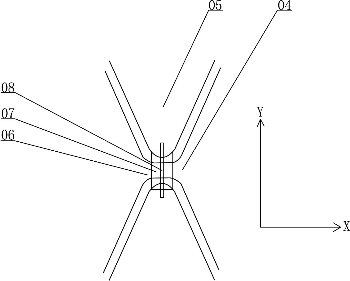
[0031] Such as Figure 4 As shown, the electrode bridging connection structure of the capacitive touch screen used to curb screen interference includes a bottom connection 1 formed by a transparent conductive film, an insulating spacer 2 arranged on the bottom connection 1, and a metal film formed across The strip-shaped connection bridge 3 of the insulating spacer 2, the bottom connection 1 is used to connect the X electrode 4 extending along the X direction, the connection bridge 3 is used to connect the Y electrode 5 extending along the Y direction, and the extension direction of the connection bridge 3 The angle θ between the Z and Y directions is 20.1°.

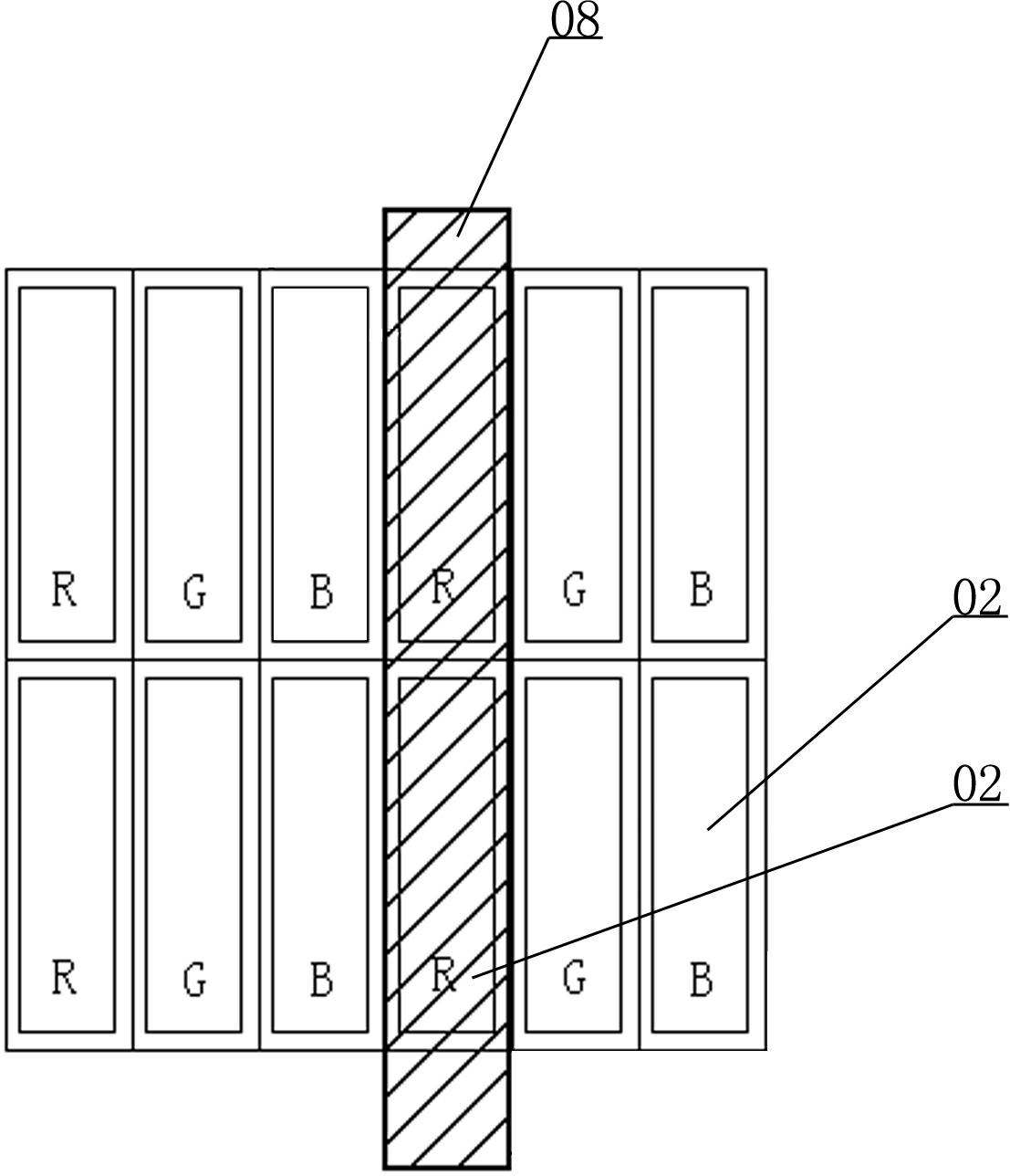
[0032] Such as Figure 5 As shown, the connecting bridge 3 covers the respective parts of the three pixels R, G, and B in the pixel in the center at the same time, therefore, it will not cause serious color shift in this pixel, making the color of the pixel more real and lifelike; Adjacent pixels are also partially cov...

Embodiment 2

[0035] Such as Figure 6 As shown, in the case that other aspects are the same as in Embodiment 1, the difference is that: the edge 6 of the connection end of the Y electrode 5 is perpendicular to the extension direction Z of the connection bridge 3, and the extension direction W of the bottom connection 1 is perpendicular to the connection bridge 3 The extension direction Z of 3 is perpendicular to each other. That is to say, the edge 6 of the connection end of the Y electrode 5 and the extension direction W of the bottom connection 1 form an angle of (90°-θ) with the Y direction, so that the bottom connection 1 can be connected at the bottom while ensuring its maximum width. 1 and the connecting bridge 3 overlap the smallest area, thereby reducing the parasitic capacitance between the X electrode 4 and the Y electrode 5, and improving the sensitivity of the capacitive touch screen. The masking situation of the pixels by the connecting bridge 3 is the same as that of the fir...

Embodiment 3

[0038] Such as Figure 7 As shown, in the case that other aspects are the same as in Embodiment 1, the difference is that: two adjacent connection ends of the Y electrode 5 are provided with protruding parts 7, and the two protruding parts 7 are staggered from each other. The opposite edges 8 of the outlet part 7 are consistent with the Y direction, the bottom connection 1 passes through the curved gap formed by the two connection ends of the Y electrode 5 in a curved form, the insulating spacer 2 and the connecting bridge 3 are arranged along the X direction, and the connecting bridge The extension direction Z of the bridge 3 is perpendicular to the Y direction, that is, the angle θ between the extension direction Z of the connecting bridge 3 and the Y direction is 90°. Such as Figure 8 As shown, in this way, the covering area of ​​each sub-pixel by the connecting bridge 3 is minimized, and the largest number of adjacent sub-pixels can be covered at the same time, reducing ...


PUM


Abstract

The invention relates to an electrode bridging connecting structure for inhibiting picture interference of a capacitance type touch screen. The electrode bridging connecting structure comprises a bottom connector made of a transparent conducting film, an insulating padding block arranged on the bottom connector, and an elongated connecting bridge being made of a metal film and bridging over the insulating padding block, wherein the bottom connector is used for connecting an electrode X extending along an X direction, the connecting bridge is used for connecting an electrode Y extending along a Y direction, and an inclined angel is formed by the extending direction and the Y direction of the connecting bridge. By the adoption of the electrode bridging connecting structure, the connecting bridge is prevented from covering all subpixels, therefore the color deviation of a pixel in which the subpixels exist is inhibited; when one subpixel is covered, adjacent pixels with different colors are covered partially; when the visual angel of eyes observing a picture changes slightly, the partial covering results in the transfer of the covered area among the subpixels in a gradually varied way, therefore the flicker of display pixels, which can be observed by naked eyes, can be avoided, and picture flicker can be reduced effectively.

Description

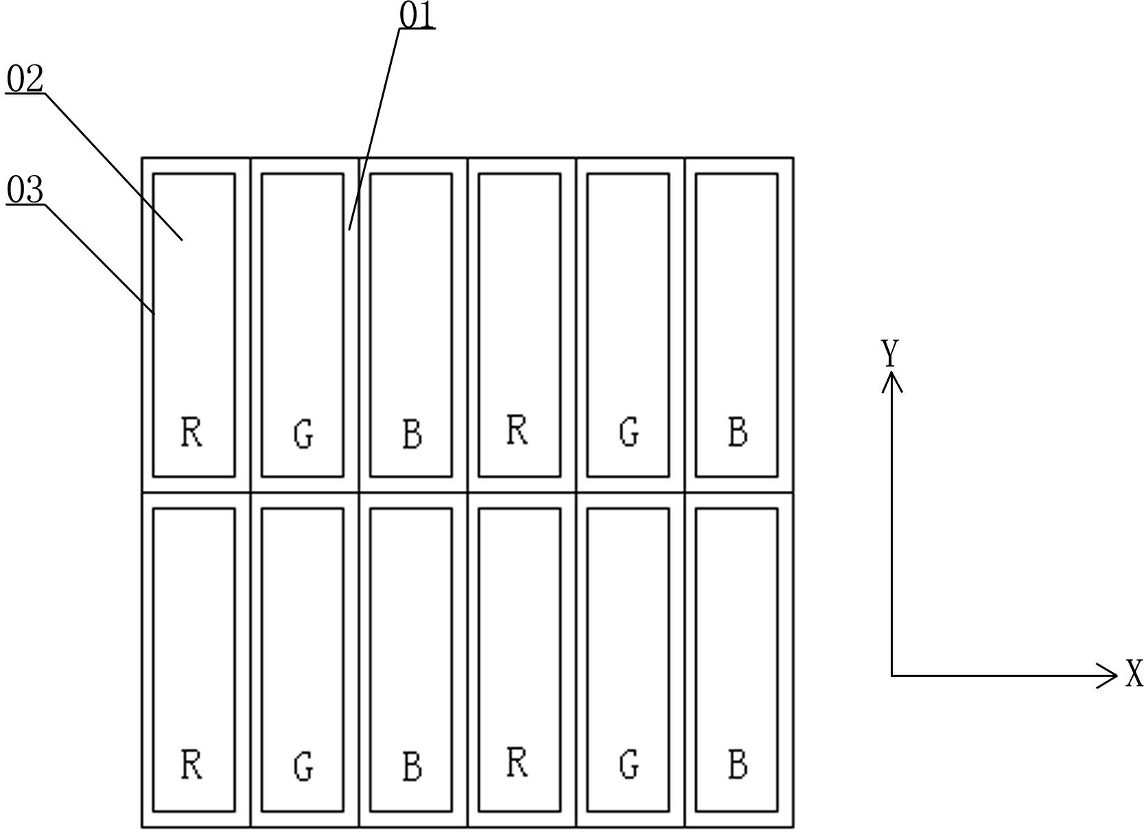
technical field [0001] The invention relates to an electrode structure, in particular to an electrode bridging connection structure of a capacitive touch screen used to curb picture interference. Background technique [0002] Driven by Apple's iphone series products, in recent years, touch control technology has been widely used in digital products such as mobile phones and tablet computers. Among them, the use of projected capacitive touch screens has become a design mainstream. Projected capacitive touch screens (hereinafter referred to as touch screens) not only can realize multi-point touch, but also have optical advantages such as high transparency, small parallax (low thickness), and small reflection of ambient light. [0003] The touch screen is generally arranged at the front of a flat panel display, so that the images of the flat panel display can only be viewed through the touch screen. According to the current technology, a flat panel display generally has a rect...

Claims


Application Information

Patent Timeline
IPC IPC(8): G06F3/044
Inventor 林钢孙楹煌吴永俊沈奕吕岳敏林伟浩许泽宇王焰丁娟
Owner SHANTOU GOWORLD DISPLAY
Learn More