Motor synchronous control method, apparatus thereof and system thereof

A synchronous control and synchronous modulation technology, which is applied in control systems, vector control systems, motor generator control, etc., can solve problems such as large current impact, irregular waveform, increased modulation time of modulation system and complexity of modulation process, etc. Achieve the effects of reducing the peak value of the motor current, avoiding over-modulation, and improving stability and reliability

Active Publication Date: 2011-11-23
ZHUZHOU CSR TIMES ELECTRIC CO LTD
View PDF6 Cites 4 Cited by
  • Summary
  • Abstract
  • Description
  • Claims
  • Application Information

AI Technical Summary

Problems solved by technology

However, since the increase of the modulation ratio will cause the reference voltage vector to be located in the over-modulation region, the reference voltage at this time needs to be processed to achieve the purpose of modulation, so the modulation time of the modulation system and the modulation process will be increased to a certain extent. Complexity, and the running track of the stator is an irregular polygon, which makes the current impact larger and the waveform irregular

Method used


Image

  • Motor synchronous control method, apparatus thereof and system thereof
  • Motor synchronous control method, apparatus thereof and system thereof
  • Motor synchronous control method, apparatus thereof and system thereof

Examples


Embodiment Construction

[0051] The following will clearly and completely describe the technical solutions in the embodiments of the present invention with reference to the accompanying drawings in the embodiments of the present invention. Obviously, the described embodiments are only some, not all, embodiments of the present invention. Based on the embodiments of the present invention, all other embodiments obtained by persons of ordinary skill in the art without making creative efforts belong to the protection scope of the present invention.

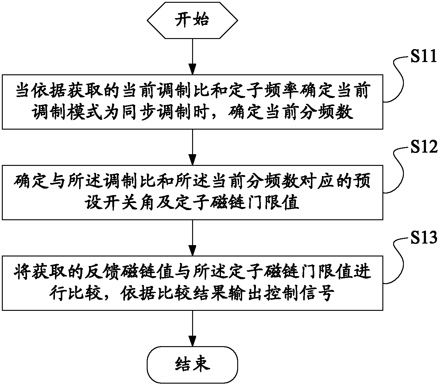
[0052] The motor synchronous control method disclosed in the embodiment of the present invention is applied in the synchronous control mode of the motor control system, and its flow is as follows figure 1 shown, including:

[0053] Step S11, when it is determined that the current modulation mode is synchronous modulation according to the obtained current modulation ratio and stator frequency, determine the current frequency division number;

[0054] The syste...


PUM


Abstract

The invention discloses a motor synchronous control method, an apparatus thereof and a system thereof. The method comprises the following steps: when determining a present modulation mode is synchronous modulation according to an obtained present modulation ratio and stator frequency, determining present frequency division amount; determining preset switching angle and a stator flux threshold corresponding to the modulation ratio and the present frequency division amount; comparing an obtained feedback linkage threshold with the stator linkage threshold, and outputting a control signal according to a comparison result. According to the motor control method disclosed in an embodiment of the invention, through a switching angle calculated in advance corresponding to a modulation ratio, the stator linkage threshold corresponding to the switching angle is determined, an actual feedback linkage threshold and the stator linkage threshold are compared, according to the comparison result a control signal is outputted, over-modulation and a further step of processing over-modulation area caused by adding the modulation ratio are avoided. Control flow of a system is simplified, working efficiency is raised, and an orbit of the motor stator becomes a regular polygon.

Description

technical field [0001] The invention relates to the field of electrical control, in particular to a motor synchronous control method, device and system. Background technique [0002] Pulse width modulation technology is widely used in AC drive system to improve the driving performance of the control system. Industrial applications require the inverter to have a wide range of speed regulation and a fast output frequency change. However, in some applications, especially medium and high-power applications, such as rail transit traction control, etc., the switching frequency of inverter switching devices is very low, so it is necessary to use segmented synchronous pulse width modulation technology to reduce current harmonics and improve inverter performance. Transformer control performance. [0003] The core idea of ​​the currently applied synchronous modulation method is to perform SVPWM fitting at a fixed position, and arrange the action sequence of the basic voltage vectors...

Claims


Application Information

Patent Timeline
IPC IPC(8): H02P21/00H02P21/14
CPCY02P80/10
Inventor 刘可安尚敬刘勇刘良杰
Owner ZHUZHOU CSR TIMES ELECTRIC CO LTD
Why Eureka
Try Eureka