Method for providing a detection signal for objects to be detected

A technology for detecting signals and objects, used in the field of providing detection signals for objects to be detected, can solve problems such as low signal-to-noise ratio and low range of action, achieve high sensitivity, improve flexibility, and save manufacturing overhead. Effect

Pending Publication Date: 2020-05-22
ROBERT BOSCH GMBH
View PDF12 Cites 0 Cited by
  • Summary
  • Abstract
  • Description
  • Claims
  • Application Information

AI Technical Summary

Problems solved by technology

Biaxial arrangements with static receive channels are usually illuminated from a large angular range and have a low signal-to-noise ratio and thus low range

Method used


Image

  • Method for providing a detection signal for objects to be detected
  • Method for providing a detection signal for objects to be detected
  • Method for providing a detection signal for objects to be detected

Examples


Embodiment Construction

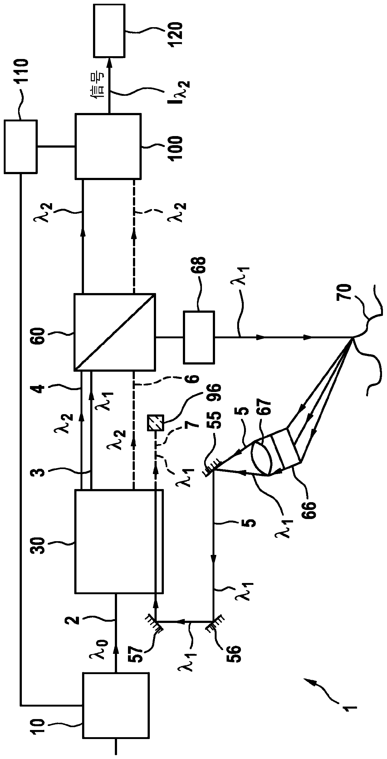
[0047] exist figure 1 A sensor device according to an embodiment of the invention is shown in .

[0048] First, by means of the laser 10 a laser with frequency f laser or wavelength λ 0 (eg 531 nm) laser beam 2 . The power of the laser 10 consists of a continuous level I 1 and pulse level I 2 The pulse-like modulation of the current source control. The laser 10 accordingly emits a continuous power P of, for example, 1 mW 1 and a pulse power P of eg 50W 2 . The pulse width is for example between 1 ns and 10 ns, preferably between 2 ns and 8 ns, especially between 4 ns and 6 ns.

[0049] The laser beam 2 is supplied to the nonlinear crystal 30 . The nonlinear crystal can be composed of (periodically poled) potassium titanyl phosphate, (periodically poled) lithium niobate, (periodically poled) stoichiometric lithium tantalate, barium borate, lithium triborate , manufactured from bismuth borate and / or potassium dihydrogen phosphate. In a first step, parametric fluoresce...


PUM


Abstract

The invention relates to a method for providing a detection signal for objects (70) to be detected, wherein by means of a first optical non-linear 3-wave process (30, 30a), from a light beam of a light source (10) having an output frequency (f<laser>), at least one first and one second light beam are generated, which have different frequencies (f<obj>, f<ref>) and wherein the first light beam having a reference frequency (f<ref>) is detected and wherein the second light beam having an object frequency (f<obj>) is emitted and, after reflection on an object (70), is received, and wherein the light beam having the output frequency (f<laser>) and the second light beam having the object frequency (f<obj>) are superimposed, and wherein by means of a second optical non-linear 3-wave process (30,30b), from the two superimposed light beams having the output frequency (f<laser>) and having the object frequency (f<obj>), a reference beam having a reference frequency (f<ref>) is generated, and wherein a detection signal is generated such that, based on the time difference between the detection of the first light beam having the reference frequency (f<ref>) and a detection of a change in the reference beam having reference frequency (f<ref>) on the basis of said superimposition, the distance (d) of the object (70) can be determined.

Description

technical field [0001] The invention relates to a method for providing a detection signal for an object to be detected. [0002] The invention also relates to a sensor device for providing a detection signal for an object to be detected. [0003] The invention also relates to a lidar scanner, in particular a microscanner. [0004] Although applicable to any sensor device, the invention is explained with reference to a LiDAR macroscanner. Background technique [0005] Known lidar macroscanners have, for example, a rotor on which optical elements such as light sources and detectors are arranged. Other known scanners have only mirrors for beam deflection as rotating elements. In a known manner, a light beam is emitted by means of a pulsed light source (for example in the form of a laser) and its reflection on the object is detected in order to determine the distance of the object from the reflected light. For this purpose, the macroscanner can have a so-called coaxial arran...

Claims


Application Information

Patent Timeline
Patent Type & Authority Applications(China)
IPC IPC(8): G01S17/10G01S7/481G01S7/486G01S7/487G01S7/4861G01S7/4865G01S17/26
CPCG01S17/10G01S7/481G01S7/4817G01S7/4865G01S7/487G01S17/894G01S17/26G01S7/4861G02F1/3501G02F1/3534G02F1/3551G02F1/39G02F1/3507
Inventor F·乌特默伦S·莱迪克P·德根费尔德-舍恩堡
Owner ROBERT BOSCH GMBH
Why Eureka
Try Eureka