
Ignition system, gas generating device for airbag, and gas generating device for seatbelt pretensioner

An ignition system and igniter technology, applied in the field of ignition systems, can solve problems such as difficult protection, insufficient protection capacity of diodes or rheostats, etc., and achieve the effects of improving reliability, simplifying structure, and eliminating malfunctions

Inactive Publication Date: 2011-11-23
NIPPON KAYAKU CO LTD
View PDF5 Cites 5 Cited by
  • Summary
  • Abstract
  • Description
  • Claims
  • Application Information

AI Technical Summary

Problems solved by technology

However, in the case of the ignition element which achieves ignition by low voltage in the present invention, since the ignition element is very sensitive to noise or static electricity, the protection capability of the diode or varistor is insufficient, and it is difficult to perform properly. Protect

Method used


Image

  • Ignition system, gas generating device for airbag, and gas generating device for seatbelt pretensioner
  • Ignition system, gas generating device for airbag, and gas generating device for seatbelt pretensioner
  • Ignition system, gas generating device for airbag, and gas generating device for seatbelt pretensioner

Examples


example

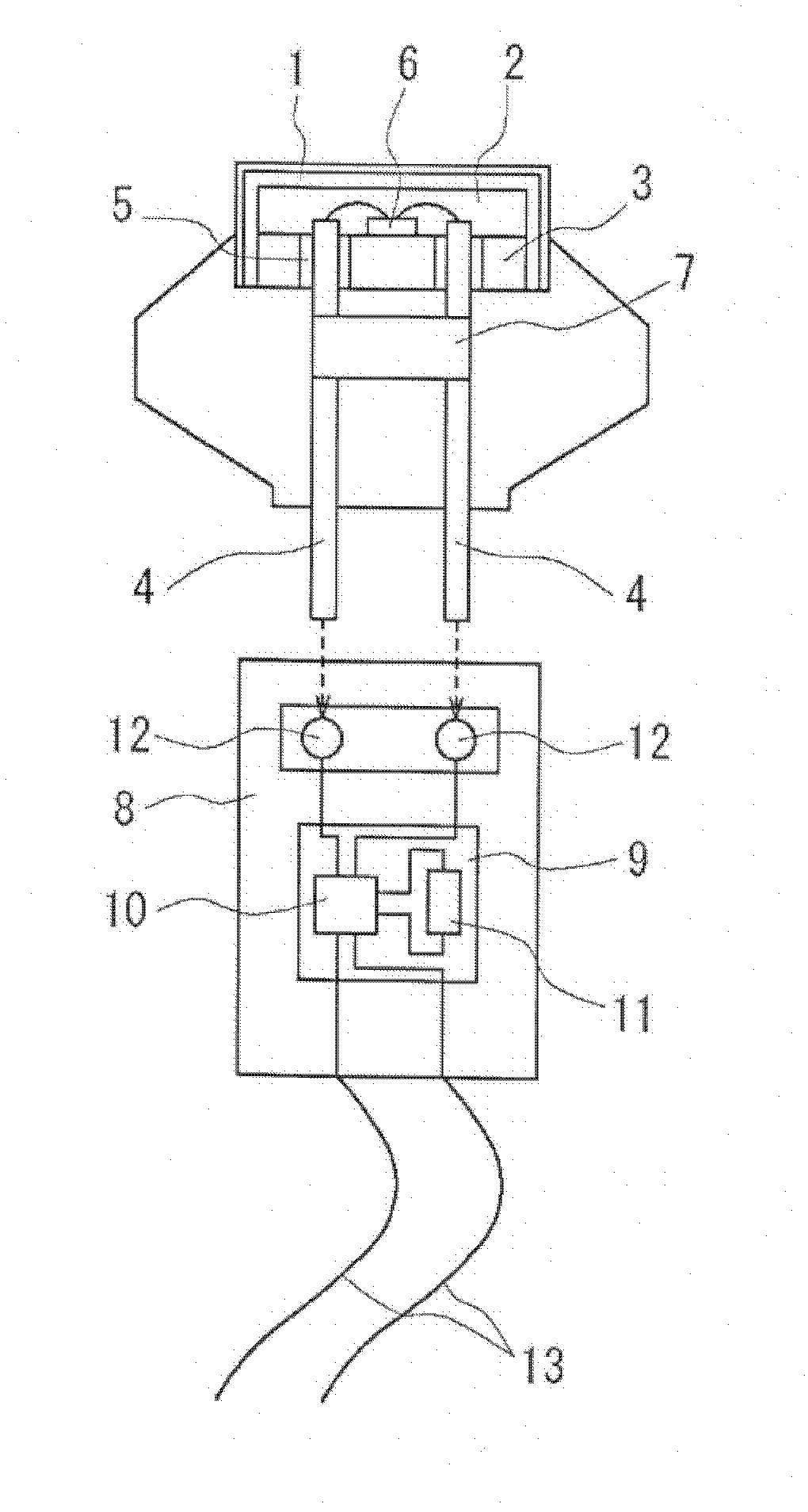
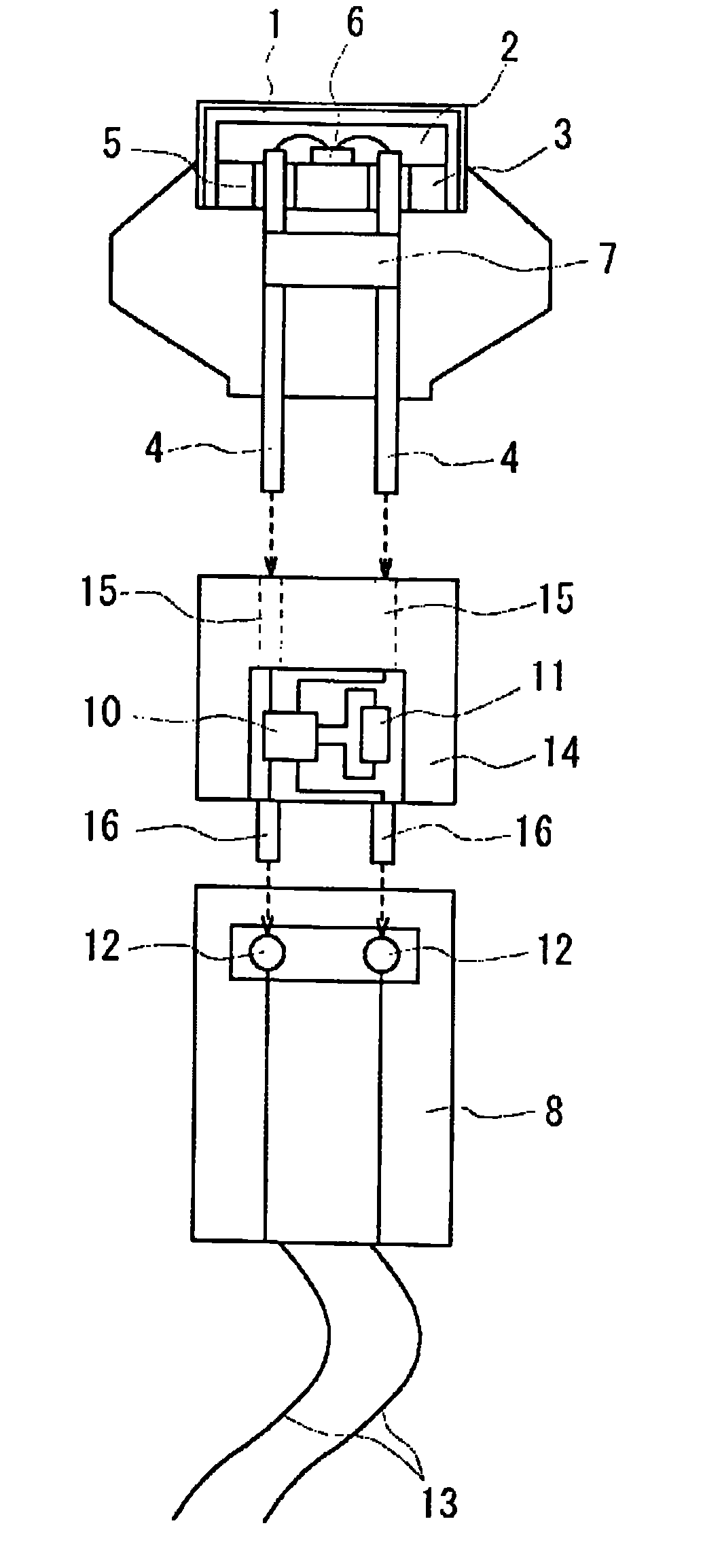
[0151] The igniter of the present invention is separated from the electrical circuit for communication and ignition, and a capacitor for electrostatic protection is mounted on the igniter side to prevent malfunction caused by static electricity or interference, and to use a fixed electrostatic capacity The discharge of the ignition capacitor is used to reliably calculate the parameters during operation.

[0152] The obtained results are shown in Tables 1 to 4.

[0153] [Table 1]

[0154] Table 1. Resistance change during static electricity resistance test due to capacitor capacity (N=5) Electrostatic application conditions (i)

[0155]

[0156] [Table 2]

[0157] Table 2. Resistance change during static electricity resistance test due to capacitor capacity (N=5) Static application conditions (ii)

[0158]

[0159] Table 1 and Table 2 show the amount of resistance change of the ignition element of the igniter due to static electricity resistance. Table 1 is the ca...


PUM


Abstract

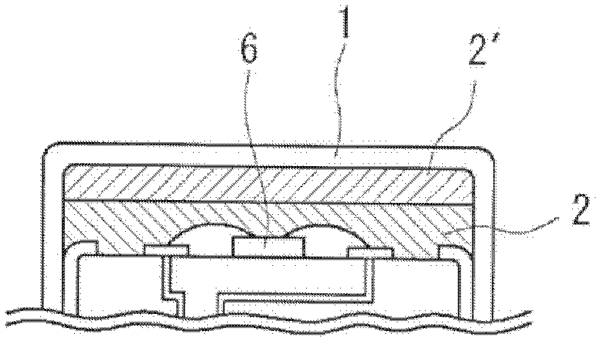
An ignition system is configured such that an igniter and an electric circuit for communication and ignition are separated from each other, is not erroneously operated by static electricity and noise, can be reliably activated by electric energy stored in an ignition capacitor, is compact, and can be produced with good productivity. An ignition system is provided with a cup body having one end open and also with a closing plug for closing the opening. Igniting powder is placed in the cup body, and an SCB chip for igniting the ignition powder when an electric current is conducted to the SCB chip is mounted on the closing plug. The ignition system is also provided with an igniter formed by electrically connecting the SCB chip to electrode pins and also with a connector for connecting the igniter to an ECU. An ASIC circuit is mounted in the connector, and ignition is performed by discharge of electricity from an ignition capacitor mounted in the ASIC circuit. A static electricity protecting capacitor is electrically connected within the igniter so as to be parallel to the SCB chip.

Description

technical field [0001] The present invention relates to an ignition system used for a gas generating device of an automobile safety device such as an airbag. [0002] Further, the present invention relates to a gas generator for an airbag and a gas generator for a seatbelt pretensioner equipped with the ignition system. Background technique [0003] As an igniter for a gas generator used to inflate an airbag installed in a car, and as an igniter for a micro gas generator (gas microgenerator) used in a seat belt pretensioner, conventional There are various electronic igniters developed. [0004] This kind of igniter generally includes a metal pin for forming an electrical connection with the outside, and an ignition element for igniting the gunpowder is provided at the other end of the metal pin. [0005] As such an ignition element, an ignition element incorporated in a printed subcircuit as disclosed in Patent Document 1 is known. [0006] On the other hand, it is consid...

Claims


Application Information

Patent Timeline
Patent Type & Authority Applications(China)
IPC IPC(8): F42B3/12B60R21/16B60R22/46
CPCF42B3/121B60R2021/26029F42B3/18F42B3/13
Inventor 小池英幸前田繁椋木大刚
Owner NIPPON KAYAKU CO LTD
Learn More