Low distortion high bandwidth adaptive transmission line for integrated photonics applications

a photonics and high-bandwidth technology, applied in waveguides, optical radiation measurement, instruments, etc., can solve the problems of difficult to achieve a final, difficult to maximize the impedance and velocity of unloaded transmission lines, and insufficient space utilization of modulators

Active Publication Date: 2011-12-08
IBM CORP
View PDF4 Cites 6 Cited by
  • Summary
  • Abstract
  • Description
  • Claims
  • Application Information

AI Technical Summary

Benefits of technology

[0009]A transmission line and method for implementing includes a plurality of segments forming an electrical path and a continuous optical path passing through the segments. Discrete inductors are formed between and connect adjacent segments. The inductors are formed in a plurality of metal layers of an integrated circuit to balance capacitance of an optical modulator which includes the transmission line to achieve a characteristic impedance for the transmission line.

Problems solved by technology

It is difficult to maximize the impedance and velocity of the unloaded transmission lines.
This makes it difficult to achieve a final, loaded characteristic impedance of the TW modulator that is close to 50-ohms while providing a reasonable velocity match to the optical signal.
A low loading factor means that the modulator is not space efficient, i.e., most of the modulator physical length does not contribute to the optical modulation.
Furthermore, passive portions of the modulator that do not contribute to modulation add optical loss.
Further, a microwave modulation signal incurs extra ohmic losses when it has to travel along longer electrodes.
A standard problem with lossy transmission lines is that the impedance of the line is a function of frequency, and this results in distortion.

Method used


Image

  • Low distortion high bandwidth adaptive transmission line for integrated photonics applications
  • Low distortion high bandwidth adaptive transmission line for integrated photonics applications
  • Low distortion high bandwidth adaptive transmission line for integrated photonics applications

Examples


Embodiment Construction

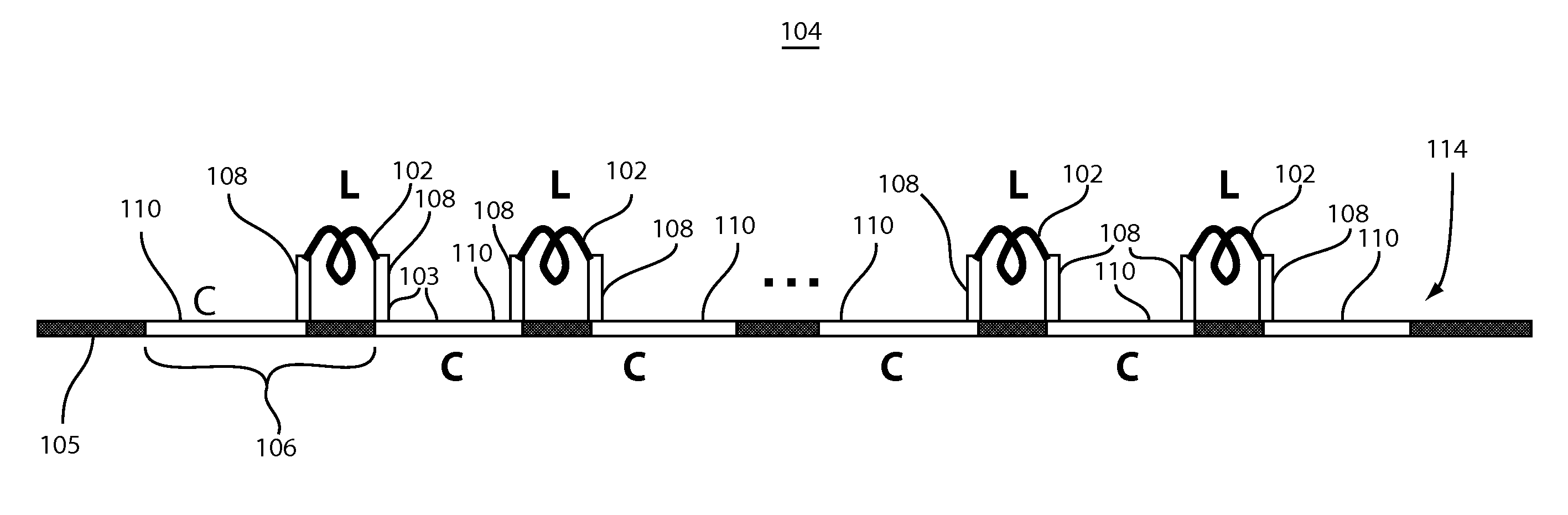
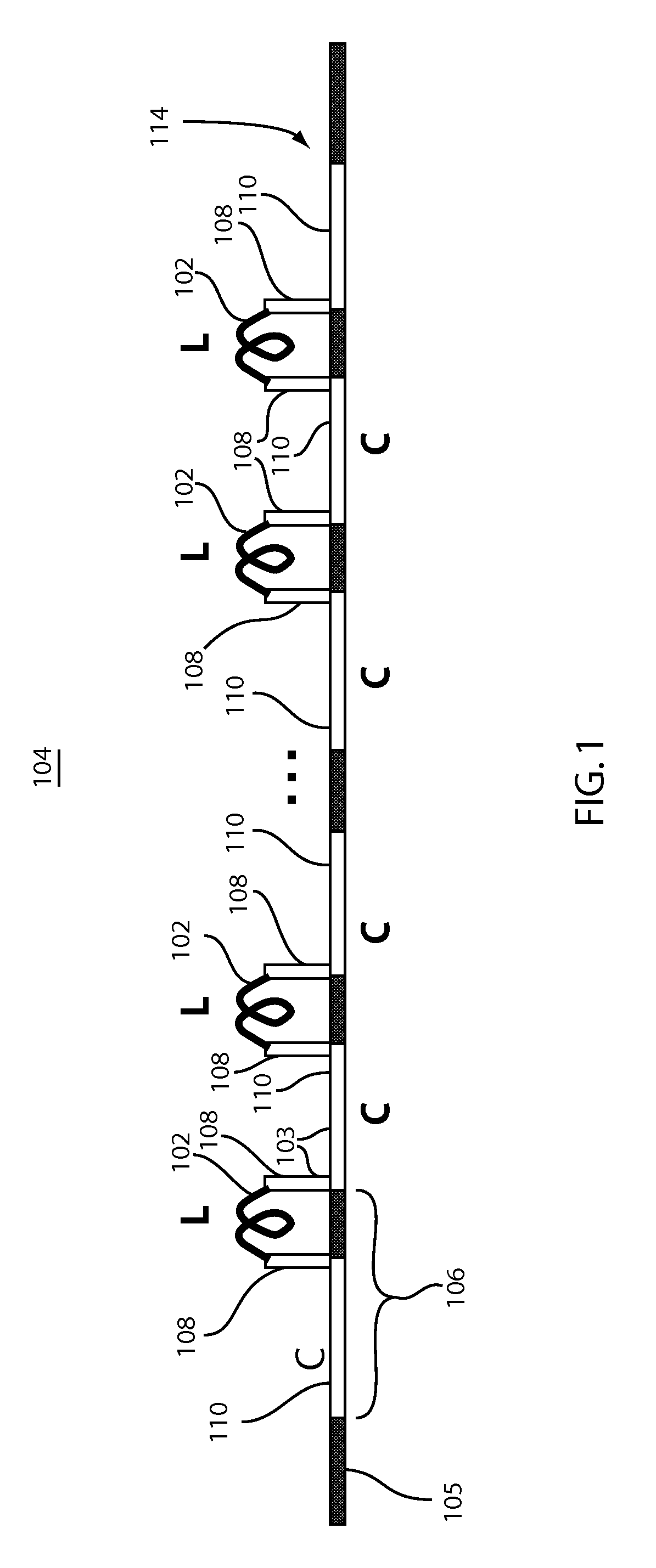
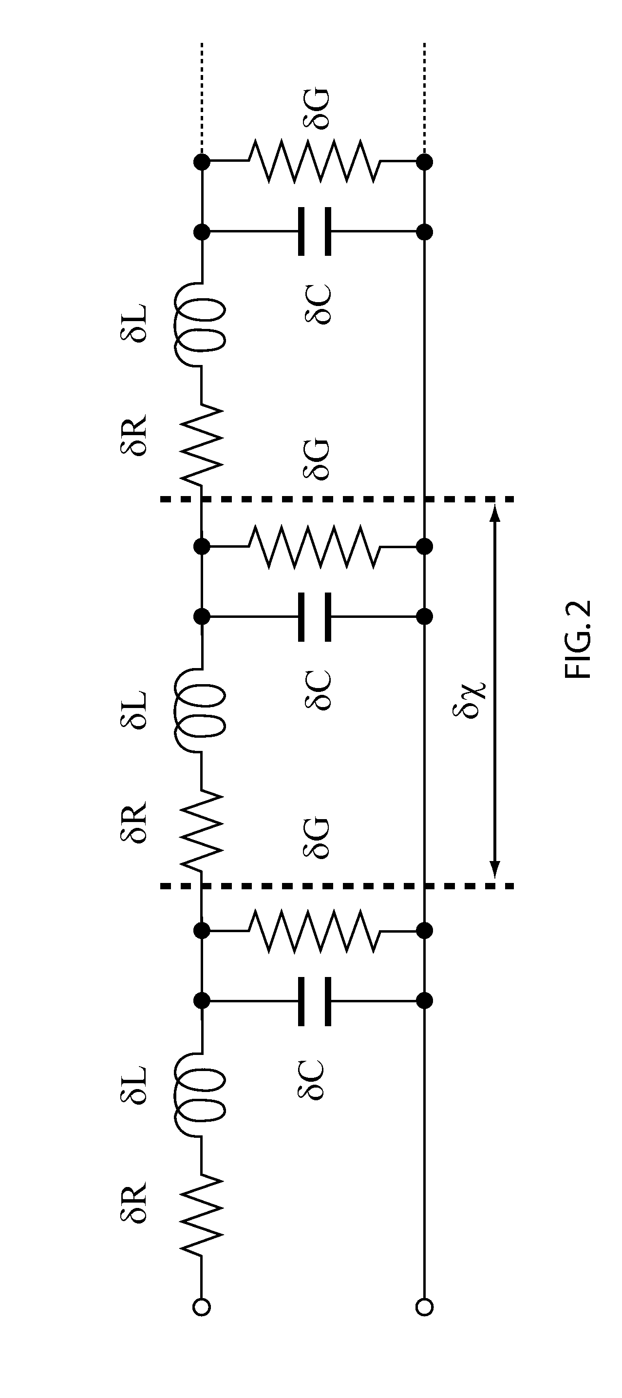
[0020]In accordance with the present principles, an optimized traveling wave (TW) structure and control circuit for semiconductor optical modulators is provided. In a particularly useful embodiment, photonic modulators are fabricated in an integrated circuit process (e.g., a complementary metal oxide semiconductor (CMOS) process) with multiple metal layers. Aspects of the present systems and methods include: distributed electrodes utilizing multi-metal layer inductors to balance optical modulator capacitance to achieve a desired characteristic impedance; low-loss optical delay lines inserted between active modulator segments to slow down the optical wave being modulated and match its velocity to the electrical modulating signal; and a tunable control circuit and method for implementing the tunable control circuit for velocity matching the electrical modulation signal and optical signal traveling in a transmission line (e.g., of an optical modulator).

[0021]Aspects of the present inve...


PUM


Abstract

A transmission line and method for implementing includes a plurality of segments forming an electrical path and a continuous optical path passing through the segments. Discrete inductors are formed between and connect adjacent segments. The inductors are formed in a plurality of metal layers of an integrated circuit to balance capacitance of an optical modulator which includes the transmission line to achieve a characteristic impedance for the transmission line.

Description

BACKGROUND[0001]1. Technical Field[0002]The present invention relates to transmission lines and more particularly to systems and methods for adaptive transmission lines that provide low distortion without sacrificing high transmission rates.[0003]2. Description of the Related Art[0004]Very high-speed optical modulators (e.g., greater than 20 Gb / s) are usually implemented as traveling wave (TW) structures. The TW configuration attempts to distribute capacitance of a long modulator such that it presents a reasonable characteristic impedance to a driver circuit instead of a large lumped capacitance. The TW configuration attempts to match the velocity of a microwave modulation signal traveling along an electrode with an optical wave being modulated which is also moving along the electrode.[0005]An ideal, lossless transmission line is designed to have a characteristic impedance (Z0U) and microwave velocity (vpU) that are both higher than final loaded design targets (Z0L, vpL) when the tr...

Claims


Application Information

Patent Timeline
Patent Type & Authority Applications(United States)
IPC IPC(8): H03L7/00H01P3/02
CPCG02F1/0121G02F1/025G02F2202/10G02F2201/127G02F2201/20G02F1/0356G02F1/01H04B3/40
Inventor GREEN, WILLIAM M.RYLYAKOV, ALEXANDER V.SCHOW, CLINT L.VLASOV, YURII A.
Owner IBM CORP
Why Eureka
Try Eureka