Printing machine flash oven height synchronous adjustment mechanism

A technology for synchronous adjustment and printing machines, applied to printing machines, general parts of printing machinery, printing, etc., can solve the problems of small operating space, unreasonable force, poor moving stability, etc., and achieve the effect of smooth movement and convenient operation

Inactive Publication Date: 2011-11-30
常州市奥伦自动化设备有限公司
View PDF0 Cites 4 Cited by
  • Summary
  • Abstract
  • Description
  • Claims
  • Application Information

AI Technical Summary

Problems solved by technology

Depend on figure 1 , figure 2 It can be seen from the structure shown that the support mode of the existing flash oven 1 is a unilateral overhanging support structure. Although the flash oven 1 is adjusted by the screw nut lifting adjustment mechanism to realize synchronous lifting adjustment, the force of the two guide rods 2 is unreasonable. The force between the guide rod 2 and the guide sleeve 4 is unilateral, and the resistance of the flash oven 1 is relatively large when it rises or falls, and the stability of the movement is very poor, which is prone to crawling
At the same time, the lifting hand wheel 7 is arranged in the middle of the two guide sleeves 4, and is located in the lower section, so the operating space is small and the operator is very inconvenient

Method used


Image

  • Printing machine flash oven height synchronous adjustment mechanism
  • Printing machine flash oven height synchronous adjustment mechanism
  • Printing machine flash oven height synchronous adjustment mechanism

Examples


specific Embodiment approach

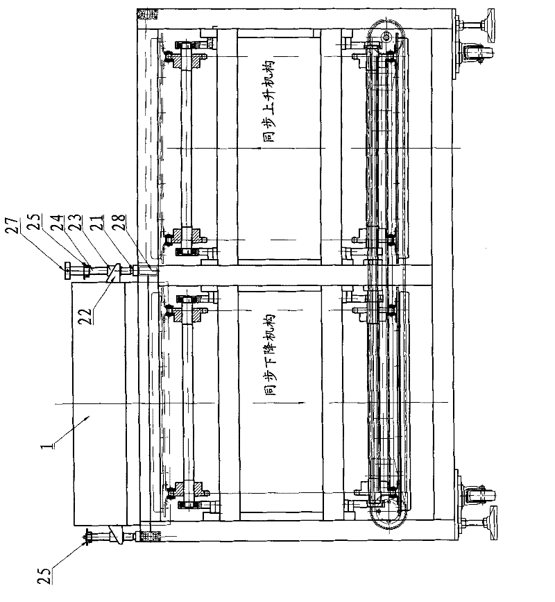
[0017] The printing machine flash oven height synchronous adjustment mechanism, such as Figure 3 ~ Figure 5 As shown, it includes frame 21, lug seat 22, threaded sleeve 23, screw rod 24, synchronous sprocket 25, chain 26, hand wheel 27 and flash oven 1, is provided with four lugs symmetrically on the left and right sides of flash oven 1 Seat 22, the center of the plane determined by the four ear seats 22 coincides with the center of gravity of the flash oven 1, four threaded sleeves 23 are fixed on the ear seats 22, and four screw rods 24 are screwed in the threaded sleeves 23 respectively. The upper end of 24 is fixedly installed a synchronous sprocket 25, and four synchronous sprockets 25 are in the same plane, and chain 26 is sleeved on the four synchronous sprockets 25, and the lower end of screw rod 24 is rotatably fixed on by limit seat 28. On the frame 21, a handwheel 27 is housed on a screw rod 24. Also be provided with tensioning sprocket 29 on frame 21, tensioning ...


PUM


Abstract

A height synchronous adjustment mechanism for a flash oven of a printing machine, including a frame, ear seats, threaded sleeves, screws, synchronous sprockets, chains, handwheels, and a flash oven. The four ear seats are symmetrically arranged on the left and right sides of the flash oven, and the flash oven The center of gravity is supported by four threaded sleeves, and a synchronous sprocket is fixedly installed on the upper end of each screw, and is in the same plane. The chain is set on the four synchronous sprockets, and the lower end of the screw is rotatable through the limit seat Fixed on the frame, with a hand wheel on a screw rod. As long as any one of the synchronous sprockets is rotated, the other three synchronous sprockets will rotate at the same time. Since the synchronous sprockets are fixedly installed on the screw, the rotation of the synchronous sprocket will drive the screw to rotate, thereby driving the threaded sleeve to rise and fall to realize the lifting of the flash oven. Adjustment, in the process of lifting, the movement is smooth, and there will be no crawling phenomenon. Since the hand wheel is set above the flash oven, the operation is very convenient.

Description

Technical field: [0001] The invention relates to a flash oven part of a printing machine, in particular to a height adjustment mechanism of the flash oven part. Background technique: [0002] The printing machine includes a transfer table, a printing head, a flash oven and a transmission mechanism for the translation of the transfer table. The printed fabric is pasted on the transfer table. The directional translational transmission between each printing head ensures accurate positioning when the transfer table is transferred to the corresponding printing heads, so as to meet the accurate printing requirements of various colors during color printing; there are screen frames and scrapers on the printing heads And the scraper action mechanism, the printing head can complete the screen printing work according to the requirements of screen printing; the flash oven is set at the next station of the printing head, and its function is to surface the printing ink formed on the fabri...

Claims


Application Information

Patent Timeline
Patent Type & Authority Applications(China)
IPC IPC(8): B41F23/04
Inventor 王永鑫
Owner 常州市奥伦自动化设备有限公司
Why Eureka
Try Eureka