
Angle adjustable valve

A valve and angle technology, applied in the field of valves, can solve problems such as unreliable locking, excessive temperature of electronic components, easy loosening, etc., and achieve the effect of ensuring stability

Active Publication Date: 2011-11-30
SHANGHAI BAOLONG AUTOMOTIVE CORP
View PDF5 Cites 11 Cited by
  • Summary
  • Abstract
  • Description
  • Claims
  • Application Information

AI Technical Summary

Problems solved by technology

Therefore, this sensor and valve need to overcome the following problems: the high-speed rotation of the tire (and due to changes in speed and road surface roughness), resulting in changes in the size of the centrifugal force, resulting in constant changes in the radial load on the tire valve of the car, making it installed after the lock It is unreliable and easy to loosen; the rim of the tire is arc-shaped, and the radius size, arc size and shape are different, and the electronic signal box of the installed car tire valve is not easy to fit the rim
However, after long-term use, the adhesive force of the glue itself changes, causing it to fall off
Moreover, since the electronic signal box is closely attached to the rim made of steel or aluminum, the temperature during braking is quickly transferred to this, so that the internal electronic components are in a high temperature state, causing the temperature of the electronic components to sometimes exceed its capacity. Tolerable limit
[0006] There is also a prior art that plastic-seals the valve and the electronic signal box together. For this reason, the electronic signal box and the valve body cannot be rotated and adjusted. Suitable for one size rim
For this reason, there have been some attempts to adjust the electronic signal box and the valve, but these attempts are difficult to ensure the stability of the structure, and the structure will still loosen under long-term vibration

Method used


Image

  • Angle adjustable valve
  • Angle adjustable valve
  • Angle adjustable valve

Examples


Embodiment Construction

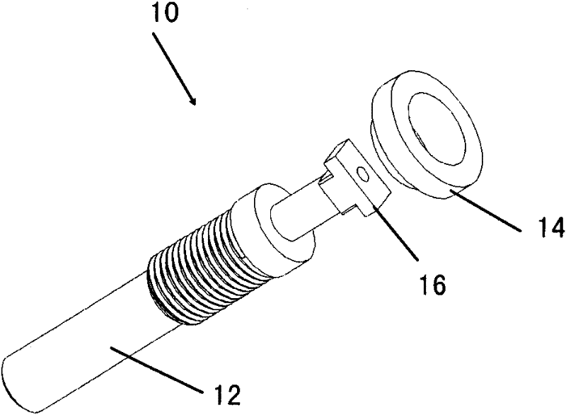
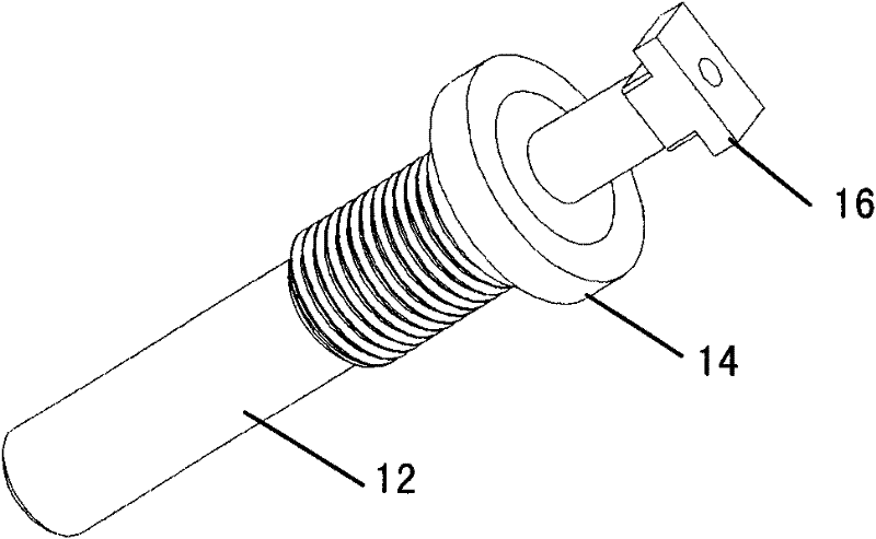
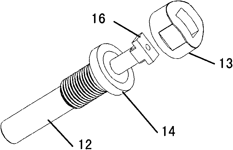
[0020] Figure 1-4 The basic structure of the valve and its assembly process of an embodiment of the present invention are shown. The valve described here does not cover the TPMS electronic signal box part. refer to Figure 1-4 As shown, the valve 10 includes a mouth stem 12 , a mouth stem cap 13 and a rubber pad 14 . In addition, the valve 10 also includes a nut 15, which will be referred to later Figure 8-10 describe. Most of the rod sections of the mouth rod 12 are smooth, and only some of the rod sections have threads. And the end of the mouth rod 12 has a rectangular stopper 16 . The rubber pad 14 and the mouth rod cap 13 are sequentially sleeved on the mouth rod 12 . In this embodiment, the outer contour of the mouth rod cap 13 may be a curved surface. The rubber pad 14 plays a role of sealing, but it can be understood that other elastic sealing pads or sealing means can also be used instead of the rubber pad 14 .

[0021] Figure 5-7 The assembly process of the ...


PUM


Abstract

The invention discloses an angle adjustable valve which is arranged on a wheel rim of the automobiles, the wheel rim possesses a wheel rim surface and an inclined surface. The valve comprises a nozzle rod, a nozzle rod cover, nuts and a sensor. The nozzle rod is provided with a screw thread segment, and the end part of the nozzle rod is provided with a stop part. The nozzle rod cover is sleeved on the nozzle rod. The sensor is provided on the wheel rim surface of the wheel rim and used for detecting and emitting the air pressure of the tires. The sensor is provided with a shell, a connecting slot is provided on the shell, the connecting slot is provided with a first side and a second side which is opposite to the first side, wherein the first side forms a first curved surface. One end of the nozzle rod is connected with the shell and extended out of the tire from a rim hole of the wheel rim. The stop part of the nozzle rod passes through the connecting slot and pressed on the first curved surface by rotating at an angle for stopping the separation of the nozzle rod and the shell. When the nuts is being screwed in the screw thread segment of the nozzle rod, the end face of the stop part slides towards the direction of the compacted shell on the first curved surface until the angle of the nozzle rod matches with the angle of the inclined surface of the wheel rim.

Description

technical field [0001] The invention relates to an automobile valve, in particular to a valve with a tire pressure monitoring sensor (Tire Pressure Monitoring Sensor, TPMS for short). Background technique [0002] The tire pressure monitoring sensor (TPMS) is installed on the rim of the car together with the valve, and monitors the air pressure from the tire. Therefore, this sensor and valve need to overcome the following problems: the high-speed rotation of the tire (and due to changes in speed and road surface roughness), resulting in changes in the size of the centrifugal force, resulting in constant changes in the radial load on the tire valve, making it installed rear lock The tightness is unreliable and easy to loosen; the rim of the tire is arc-shaped, and the radius size, arc size and shape are different, and the installed automobile tire valve electronic signal box is not easy to fit the rim. [0003] Due to the existence of the above problems, there are not many r...

Claims


Application Information

Patent Timeline
Patent Type & Authority Applications(China)
IPC IPC(8): B60C29/06B60C23/04
CPCB60C23/0494
Inventor 谭利李威
Owner SHANGHAI BAOLONG AUTOMOTIVE CORP
Learn More